
This will be a collection of notes and a timeline of sorts as I work on exploring a new band. I will include both successes and failures. Uh, well... some of the failures at least.
Click on any of the small images to get a big version.
I have been intrigued by the idea of trying microwaves for years but I thought it would be near hopeless trying to make contacts from my location. The vast majority of 10 GHz activity is portable where one can select favorable locations. Operating portable is not an option for me. It would be my home station or nothing. I am not on a hill, my horizon is imperfect and I am a long way from any other 10 GHz stations. I was aware of rain, snow and aircraft scatter but perusing the various web pages and articles I had access to did not turn up enough information to assess my chances. I found a good amount of information on how these propagtion mechanisms work but little to nothing regarding what one could realistically expect for a given station setup. When I did find web sites or videos with information about specific QSOs that were made, there was often no information given about power or antenna gain. Over the last year or two there has apparently been a surge in 10 GHz activity. It seems this has resulted in an uptick in videos being posted to platforms such as Youtube. Still, information about equipment used was often incomplete. I also read an article by KA1GT about a very low cost 10 GHz receiving setup. This, combined with the loss of 2200 meter operation pushing me to look for a new challenge, led me to seriously consider trying 10 GHz. The other challenge is getting above the trees. Fortunately the trees top out at about 95 feet and I have two towers taller than that. One is 96 feet, the other 104 feet. While rebuilding from storm damage in 2021 I reserved a spot on a mast at 105 feet for a small 10 GHz dish.
Since I was seriously considering starting out with a low cost receive setup to explore the potential of my location, I became particularly interested in beacons. Since most 10 GHz activity is from portable operations and the majority of QSOs are coordinated in some way, it didn't seem likely I would be hearing much unless I could hear beacons. I had questions about this since beacons often have much less antenna gain than a typical 10 GHz station. I went on a search for information about hearing beacons on rain, snow, or aircraft scatter but found next to nothing. Did this mean beacons are too weak to be heard at distance using these scatter modes, or was it simply that no one was posting information?
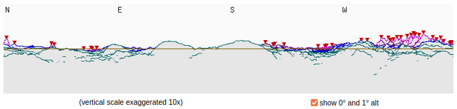
My horizon profile from planned location of 10 GHz dish generated by HeyWhatsThat
The next thing I did was join several 10 GHz and microwave forums. The people on the forums are very friendly, outgoing and generous. They seem eager to help. There I started asking questions about propagation and what to expect from my imperfect location given the size of station I felt I might be able to put together. Based on information gathered in that way, 10 GHz sounded much more promising. Over several months digging through forum archives, reading new posts and watching videos shared there, my perception of what is or might be possible continued to evolve. Even so I felt I wasn't getting a solid picture. I developed a strong perception that what is known within the microwave community regarding possibilities and expectations is largely not known outside the community. Is 10 GHz one of the best kept secrets out there? I hoped to find out.
At this point, after several months with some view "inside" the community (only by way of the forums) I still feel I have a poor understanding of what to expect, though it has greatly improved. I still perceive a large gap between knowledge inside the community and information that gets outside it, particularly in the area of possibilities and expectations. Only time and experience will show whether this perception is accurate. I may be coming to this in an unusul and particularly isolated manner. Once again I only have perceptions to guide me, but from what I can gather most newcomers to microwaves have some opportunity to connect in person with those areadly involved, including being a participant or observer in portable microwave operations. I do not have such opportunities, which makes me far more isolated and out of the loop.
I haven't asked but I might have access to a potential beacon site as well. The tower is owned by a local ham radio club. I own one of the repeaters on the tower. I know I can't afford it but I can't get the idea of a 10 GHz beacon out of my mind. In these days of very affordable 10 GHz receive systems, might beacons play an important role in attracting newcomers?
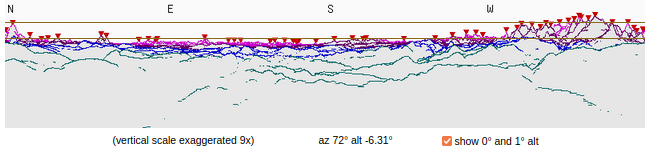
Potential beacon horizon profile generated by HeyWhatsThat
I don't want to start off on the wrong foot with the 10 GHz community I hope to join but I am one to tell it like I see it. If I am being honest, I give the 10 GHz and microwave community a failing grade on getting information out there to help prospective newcomers understand the potential. There is not enough out there to help someone who is isolated or not solidly connected to the community evaluate the prospects of the band. I find this unfortunate and disappointing. I am increasingly finding that a lot of stuff that would be very helpful in this regard, such as videos of actual reception or QSOs, is only being posted temporarily and its availability is only known within the microwave community. I will be on a mission to do whatever I can to improve the situation. As I learn and discover what can be done from my location I will post things here, on my blog, and on Youtube. I hope to have a receive-only system ready to go on the tower in the early Spring. A full transceive system is a long way off due to budget constraints.
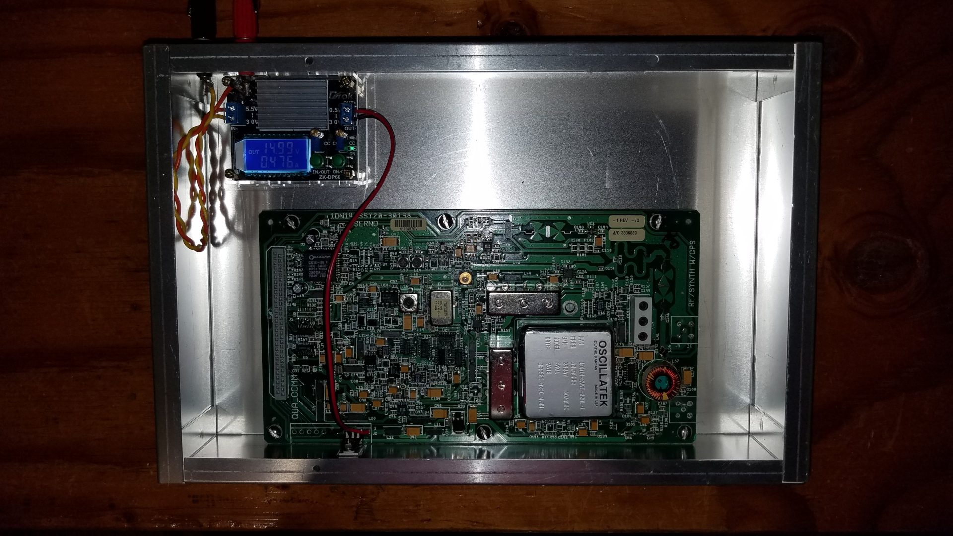
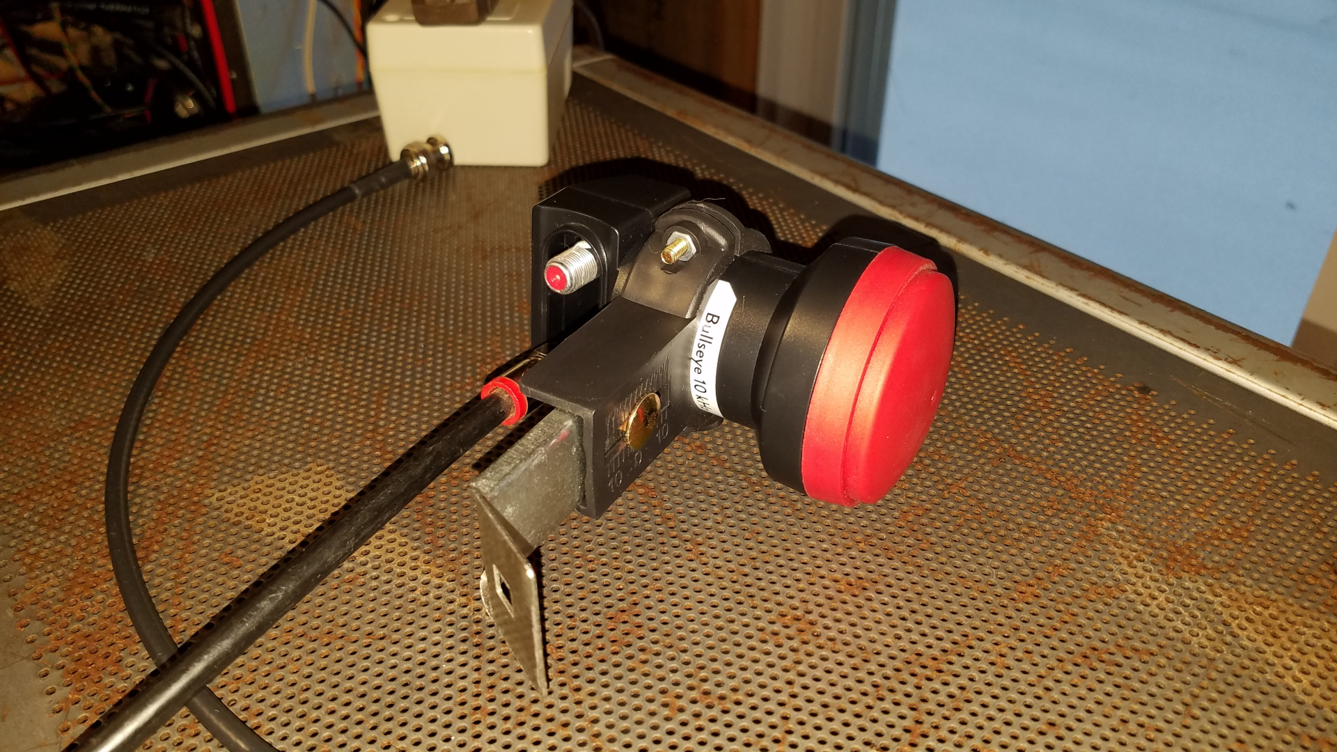
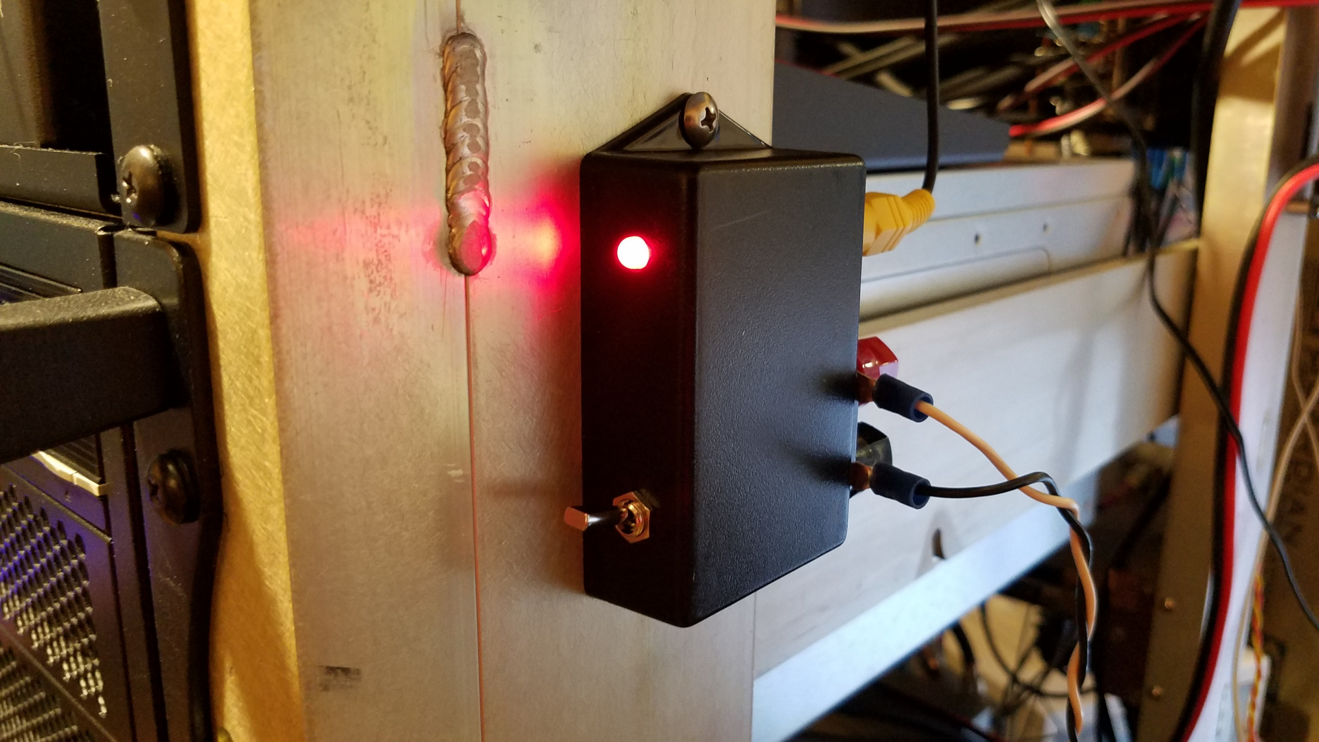
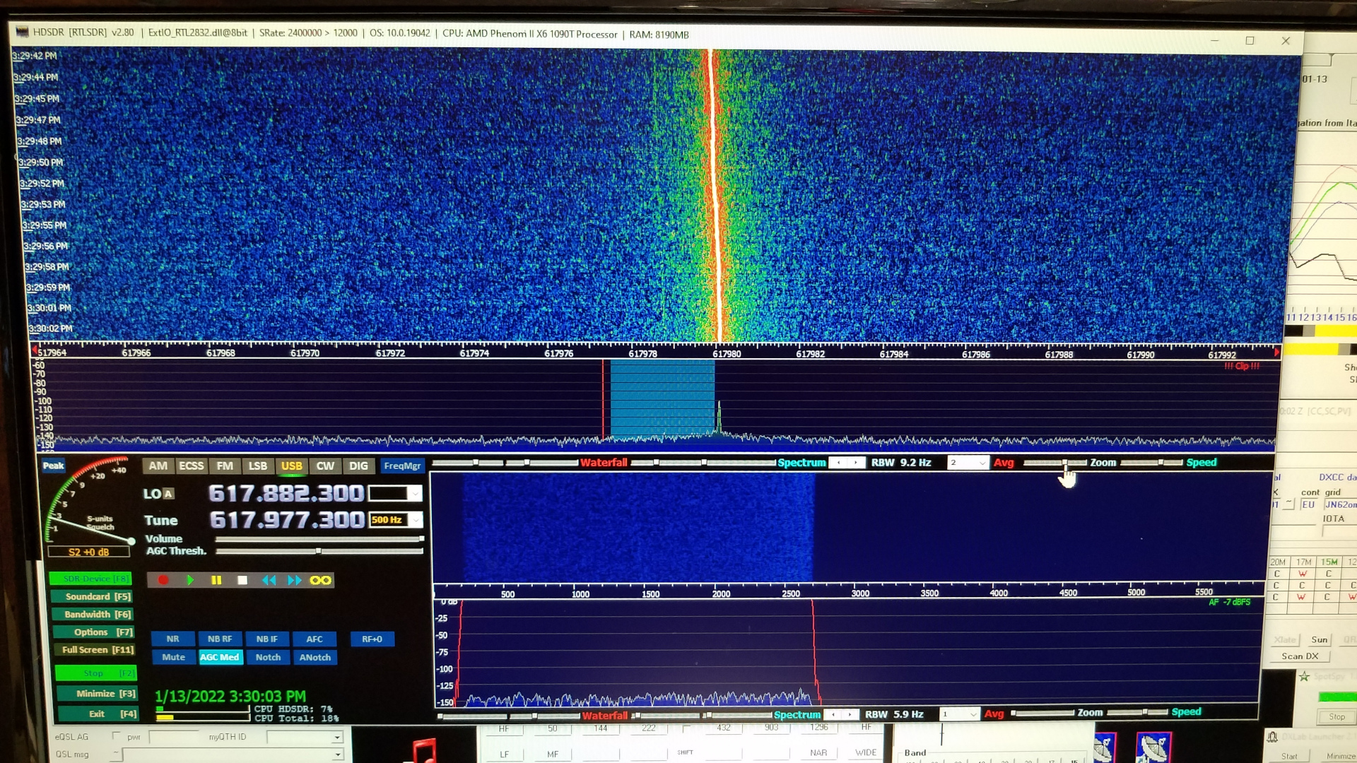
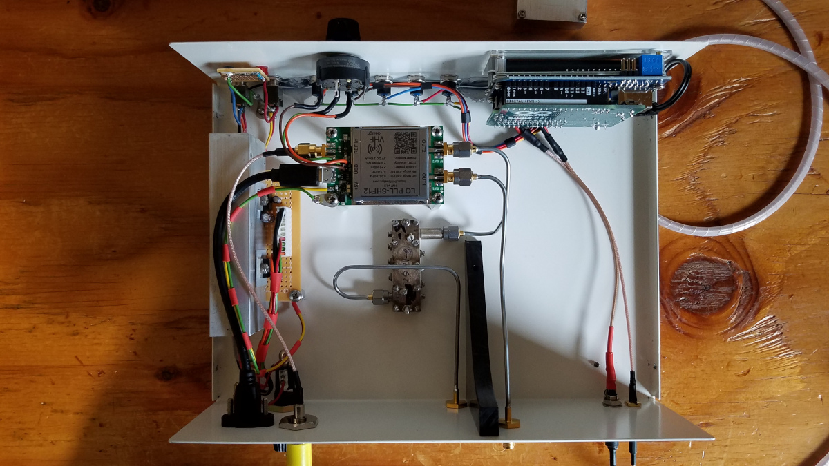
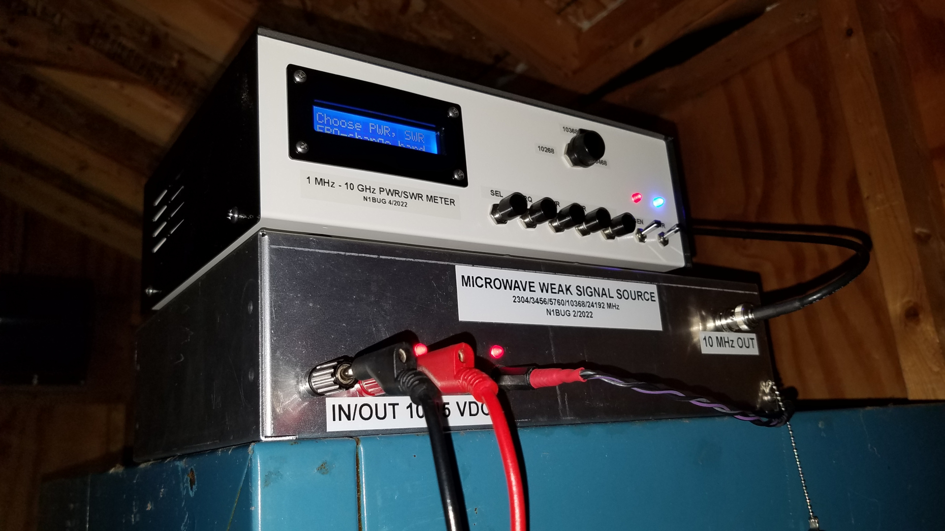
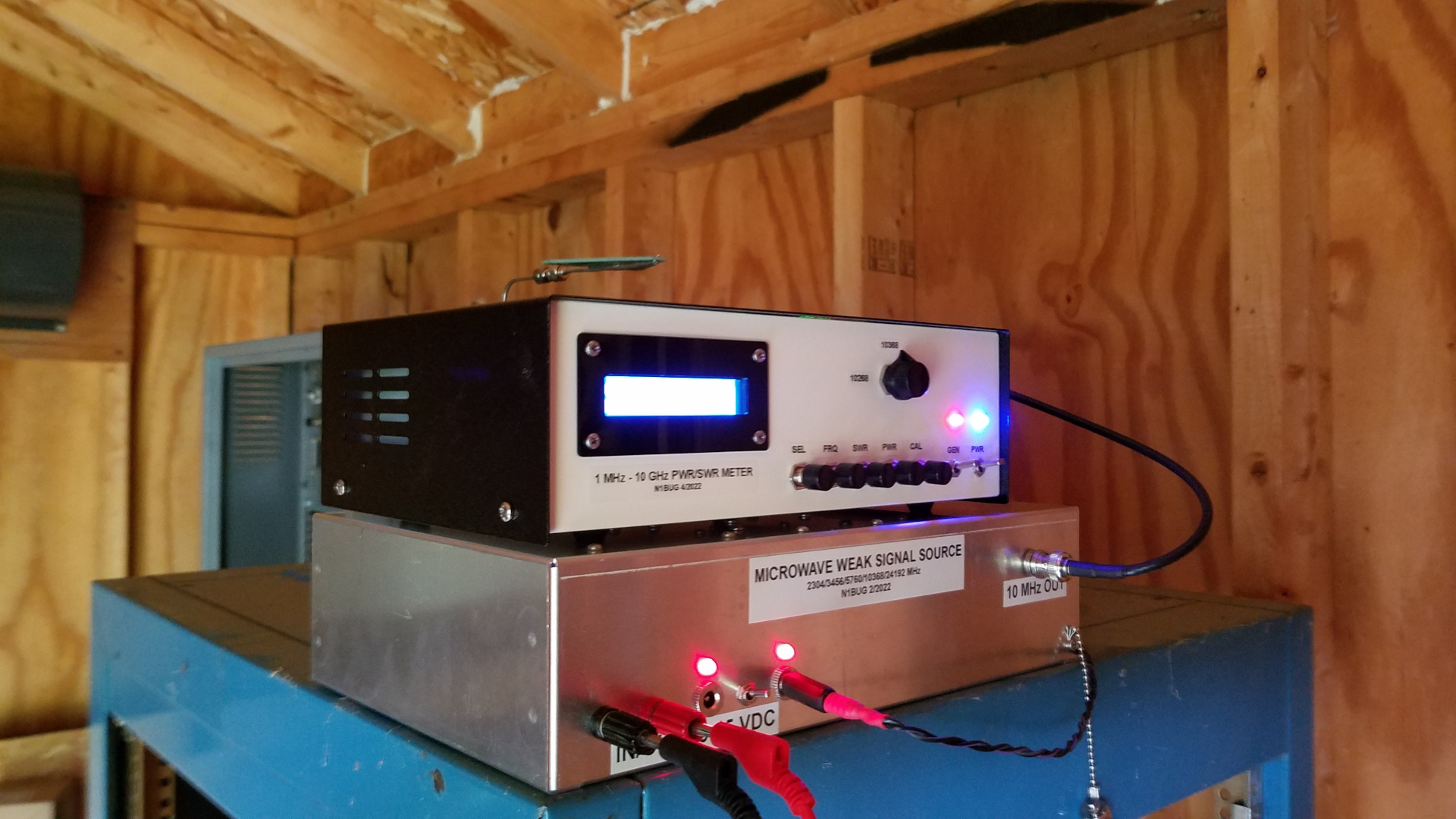
Today I did initial testing of a 10368 MHz signal source and the LNBF I hope to use for a receive-only system. The signal source is an old Qualcomm synthesizer board (thanks N1JEZ) modified to produce 1152 MHz. It should be producing harmonics that fall in several ham bands: 2304, 3456, 5760, 10368 and possibly 24192 MHz. The 10368 signal is quite strong listening with the Bullseye 10 kHz LNBF in the next room. The LNBF converts 10368 down to 618 MHz which I run into one of the cheap RTL2832 SDR receiver sticks. I mounted a switch on the side of an equipment rack to control 12V to the LNBF. At this point nothing has been calibrated. I am still using the original 10 MHz OCXO reference on the Qualcomm board, I am certain the RTL2832 stick is off frequency a bit and though the Bullseye 10 kHz is one of the more accurate if not the most accurte LNBF in terms of frequency, it is likely not perfect. Getting some of the frequency errors and drift under control is next on my list of things to do.
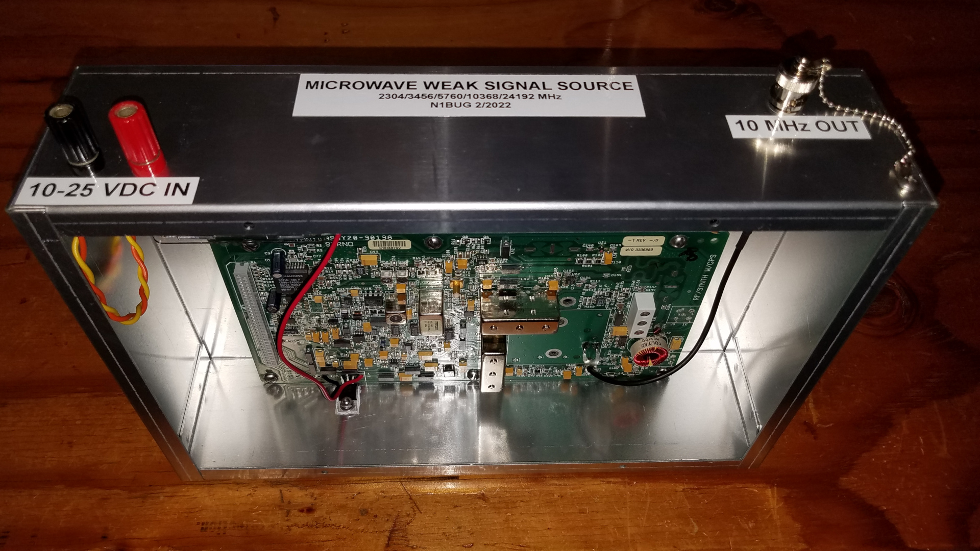
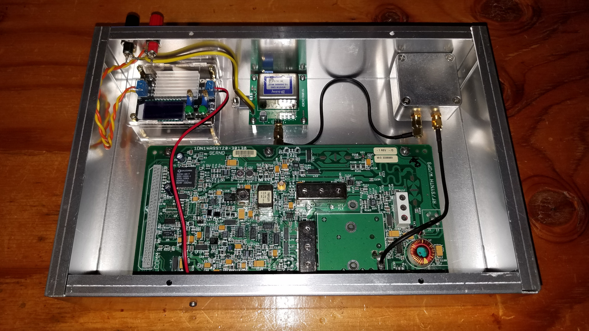
Completed work on the weak signal source. Removed 10 MHz OCXO from Qualcomm board, replaced with external Bliley NV47A1282 on a VA3TO board (thanks to VA3TO). After a day or two of testing I feel that I know where I am to within 30 Hz at 10 GHz. Oscillator aging may require frequency adjustment to maintain that level of precision but I can easily do that since I have a GPS ereferenced HP counter.
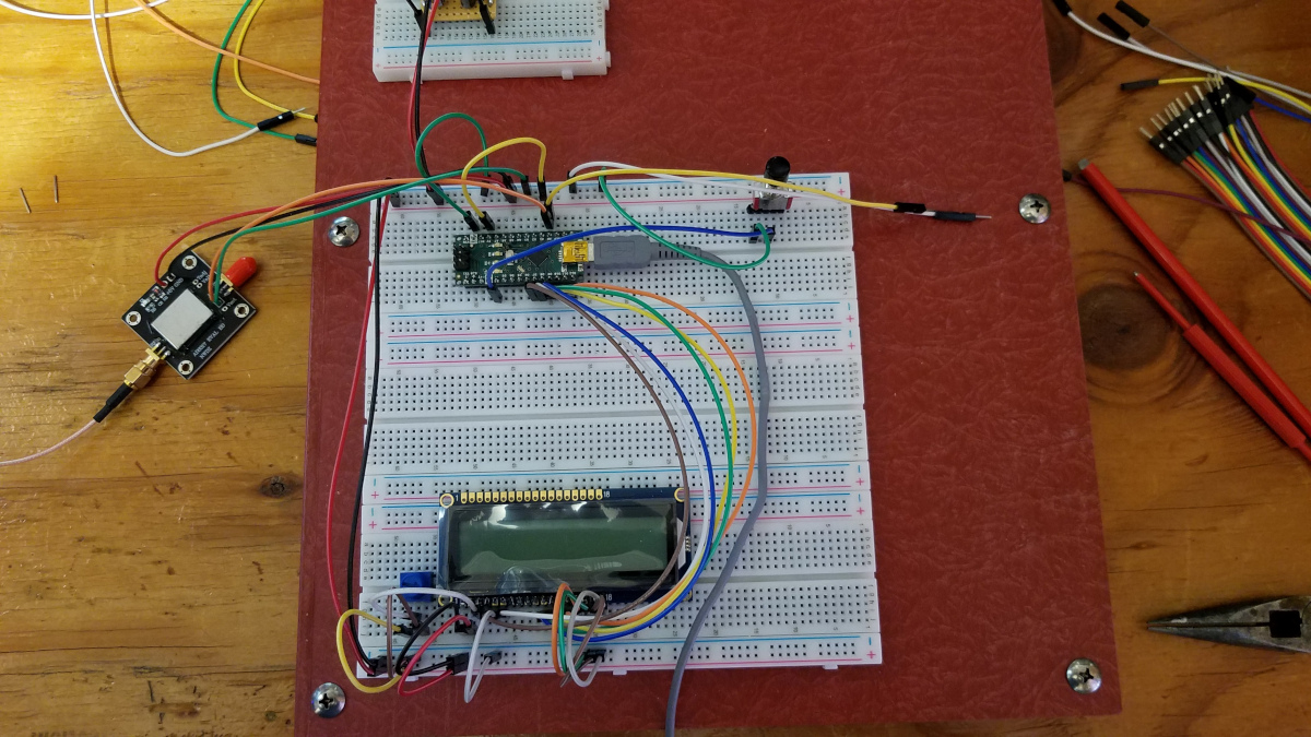
Over the past few weeks I have been working on a power and SWR (return loss) meter. The first trial run used a $25 power sensor board from China using the AD8317 chip. Others have had good luck using boards like this but mine was terrible. It was sort of OK at 1 to 2 GHz but not a good fit to the curves for 900 and 1900 MHz in the AD8317 datasheet. 2 GHz is the limit of my in-house testing capability. It was unreasonably poor at 144 MHz. That plus the board being .062" thick which I understand is not good at 10 GHz led to me lose all confidence in that board. I suspect getting a good one is a matter of luck. For the first attempt I was using the Arduino Nano. Here is a picture of this failed atteampt at the project.
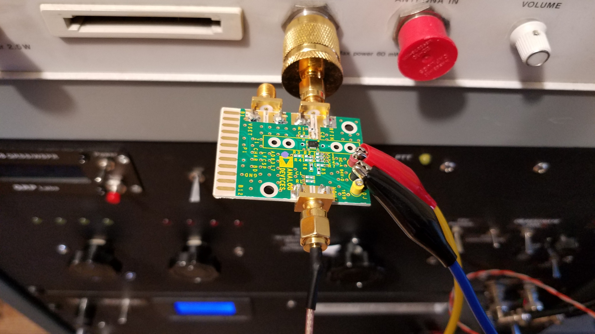
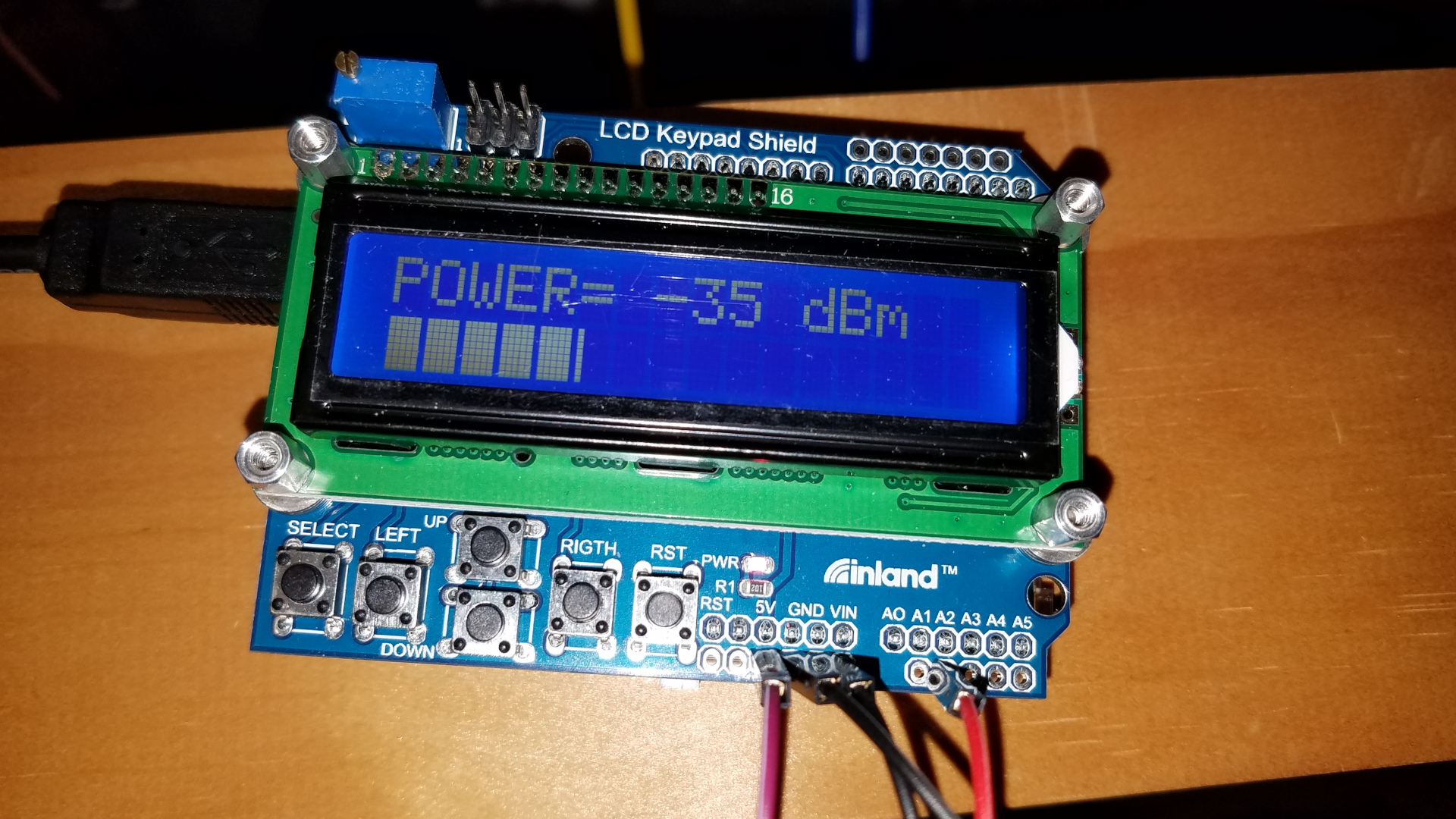
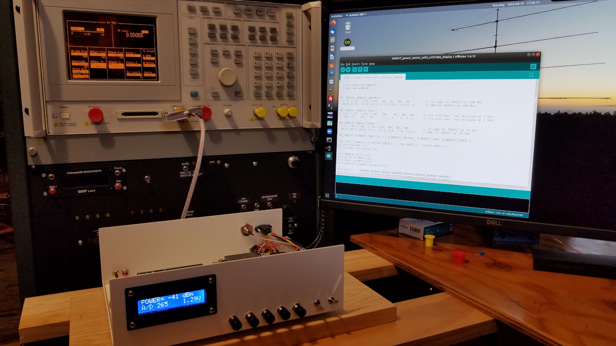
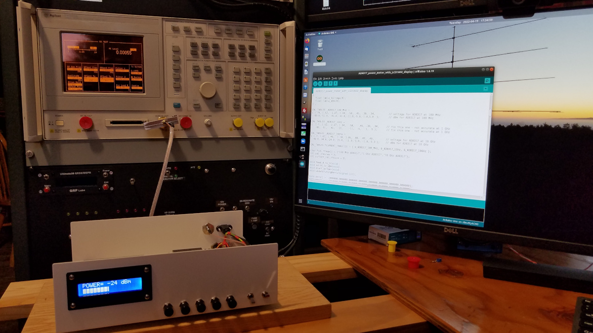
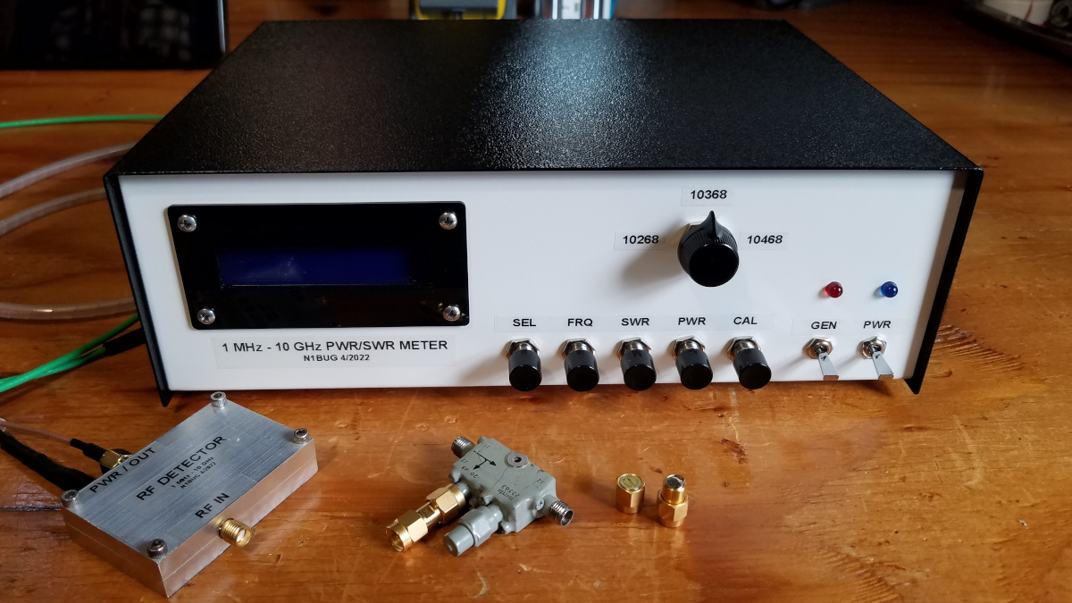
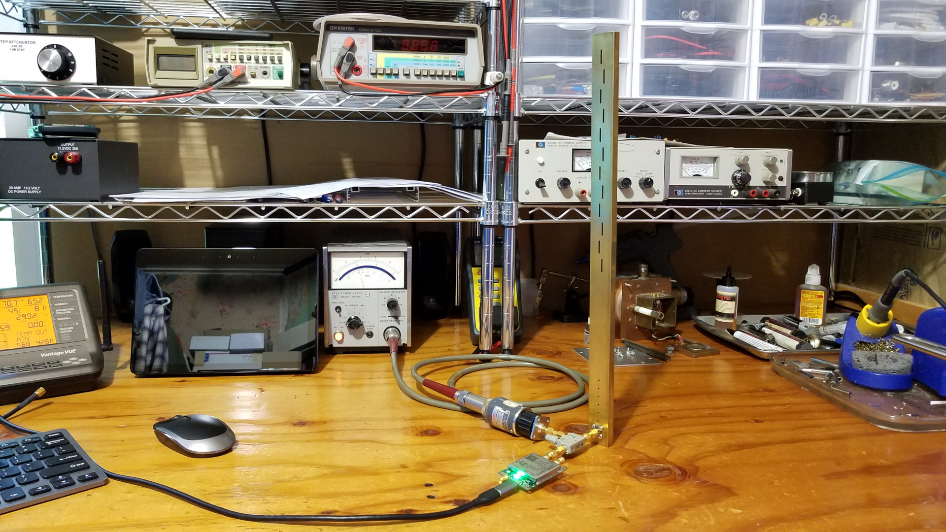
I decided to try the much more pricey ($144) Analog Devices AD8317 eval board. It looked much better. At 900 and 1900 MHz its performance closely followed curves for those frequencies in the AD8317 datasheet. At 144 MHz it looked far better than the cheap boards, though calibration was significantly different than at the higher frequencies. I also was not happy with the code I was using for the Nano. It was going to require a lot of work to get it where I wanted to end up. I used to be a fair PC software developer back in the 1990s but had not written a line of code in 20 years prior to taking on this project. I then learned of another approach and obtained different code from another 10 GHz operator who is working on a similar project. As a matter of convenience I switched to Arduino Uno R3 with LCD keypad shield. This greatly reduced the breadbording reauired, as well as conveniently provding several buttons for controlling the meter. Here are a couple pictures of the test setup with this implementation. The top line of the display shows the reading (here power in dBm) while the bottom line is a bar graph which can be very useful when tuning things.
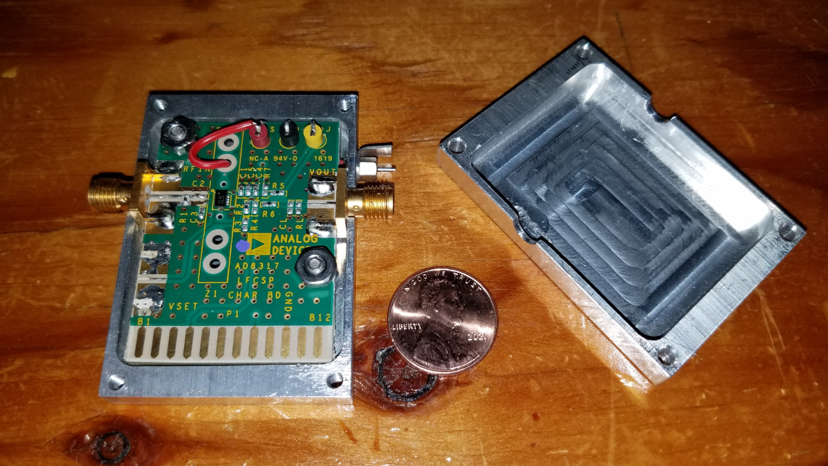
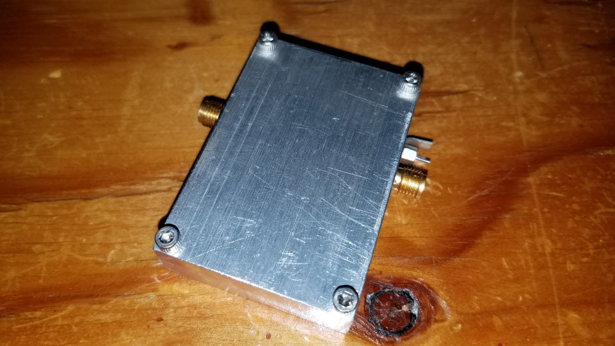
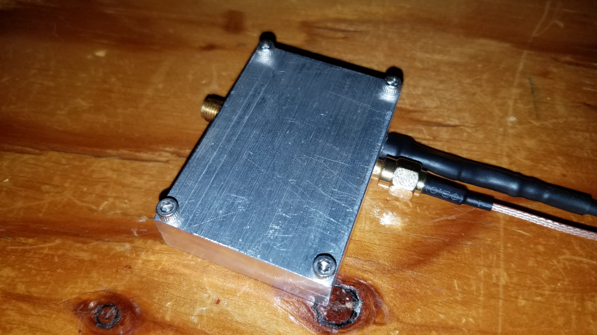
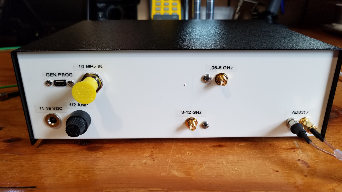
Progress has been a little slow but I have several projects in the works. Today I did final assembly on the sensor head for power and return loss measurements. A connectorized DC power feed might have been preferable but was not within my capabilities in very limited space. Small size and light weight were important goals. The connection is well strain relieved and should hold up for quite a while. The DC power feedthrough filter is a #4-40 size from Downeast Microwave. Thanks to W1GHZ for generous assistance. Several parts have been sent out for characterization on a VNA, including the directional coupler, SMA short and SMA termination for this project.
I calibrated the power sensor for all bands 1.8 MHz to 903 MHz. I also calibrated at 1000 and 2000 MHz, which is as close as I can get to the 1296 and 2304 MHz bands, but should be close enough. The reading has about 2 dB of jitter at 1.8 MHz. All higher bands are OK. Calibration changes by 3 or 4 dB as I work my way up through the bands. Useful dynamic range is 60 dB on all bands checked so far (-60 to 0 dBm). It will be less on 10 GHz but should be at least 40 dB there. I will need to send it out to be calibrated for 10368. If whoever I send it to has time, I will have it calibrated for 3400 and 5760. It would also be interesting to have it checked at 11 GHz to see if it is still useful there. That might be good to know when it comes to making return loss measurements. The calibration process was boring to some...
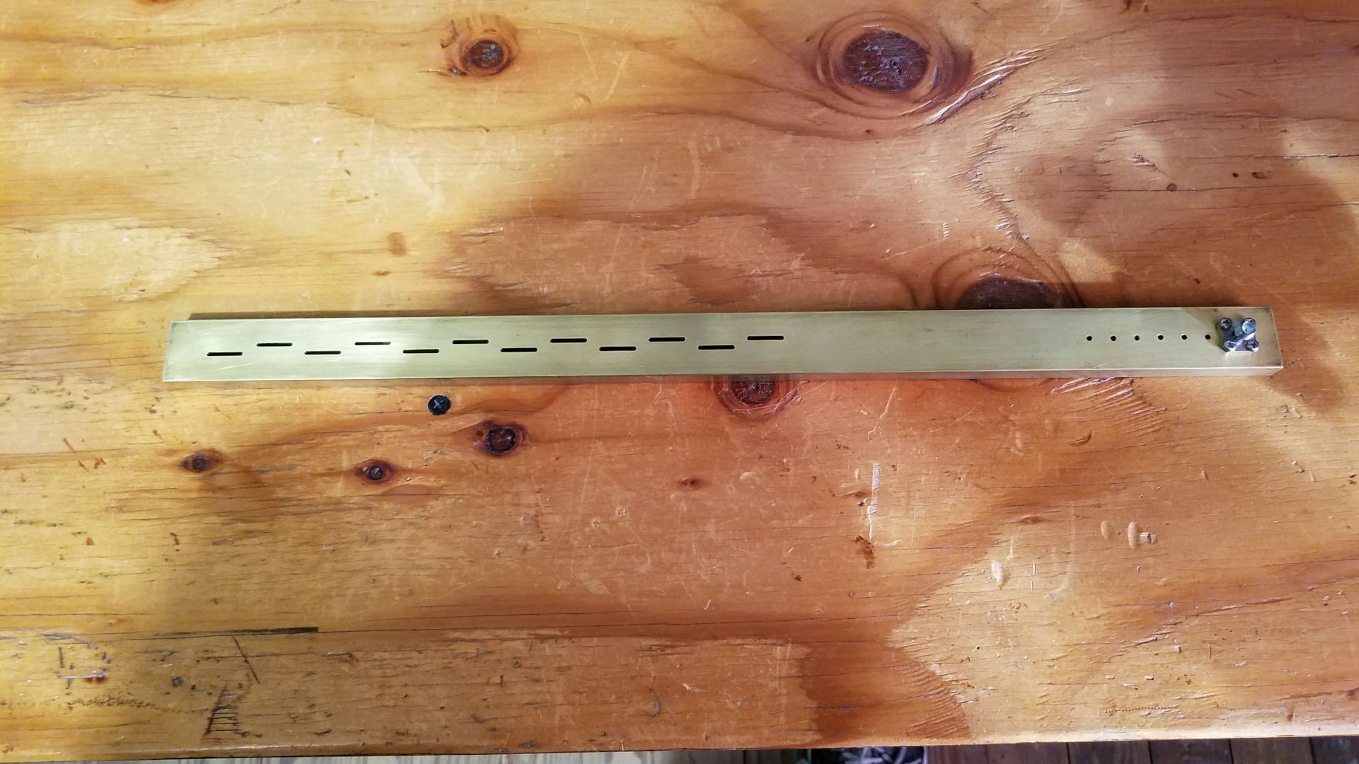
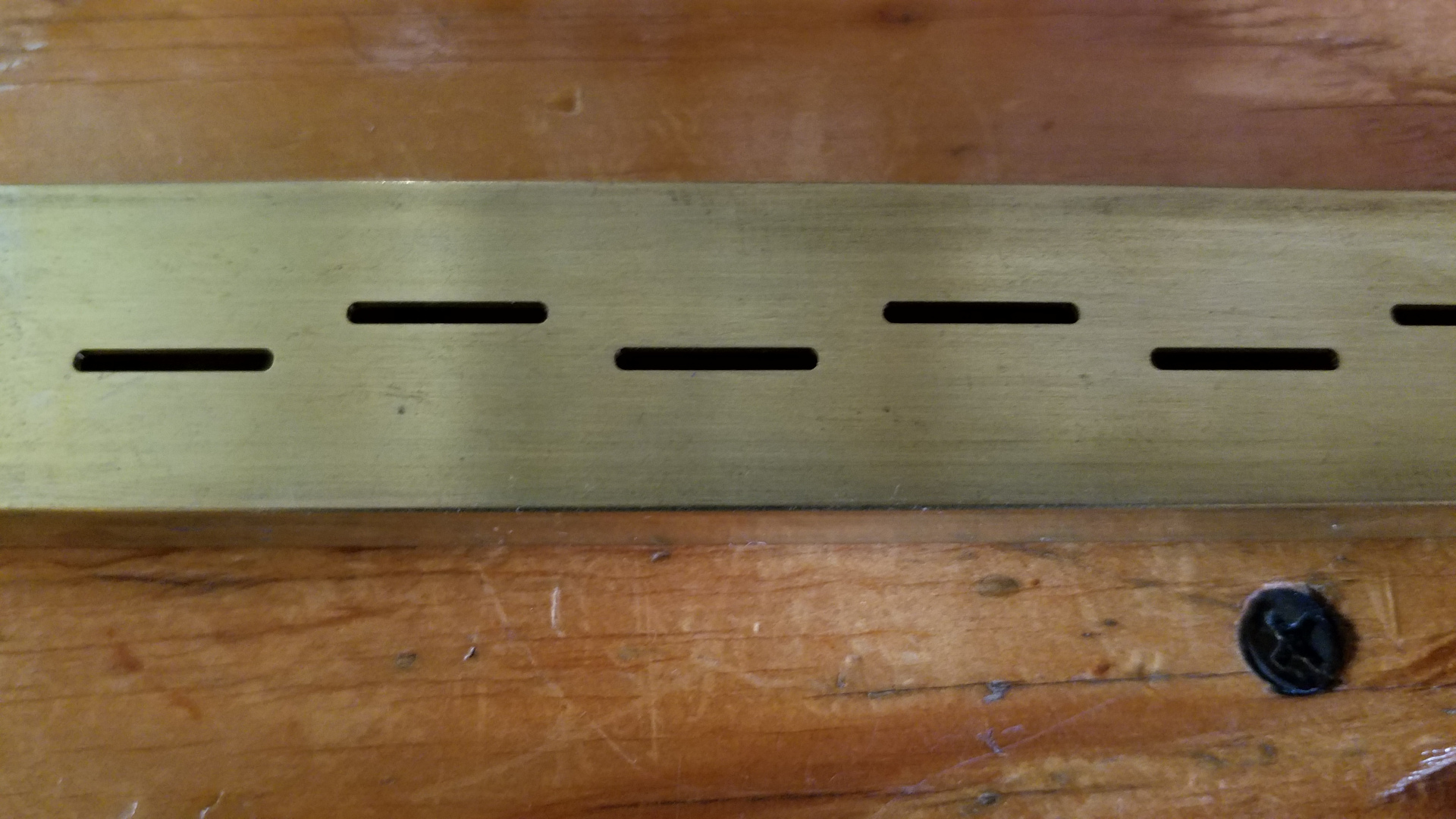
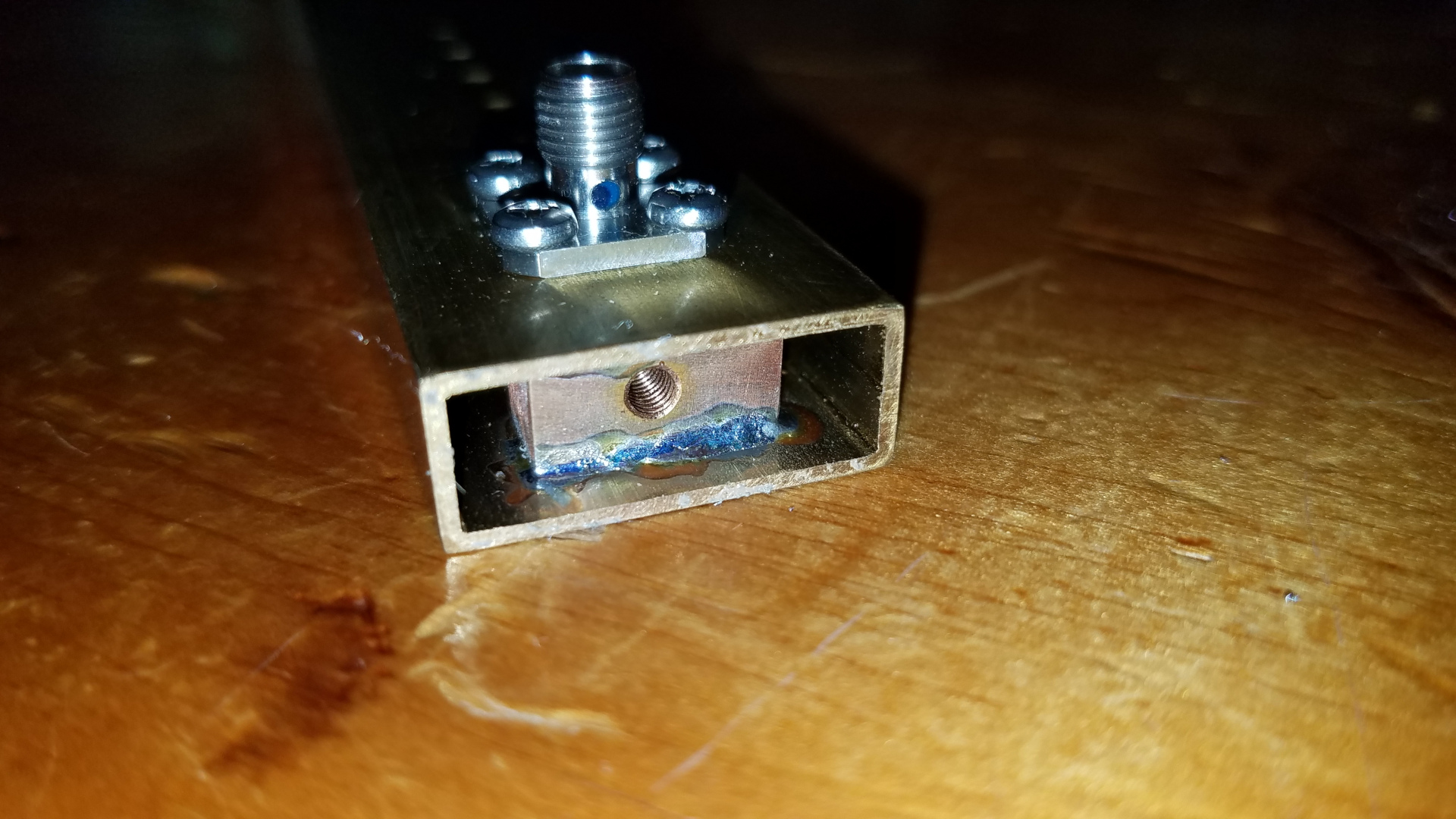
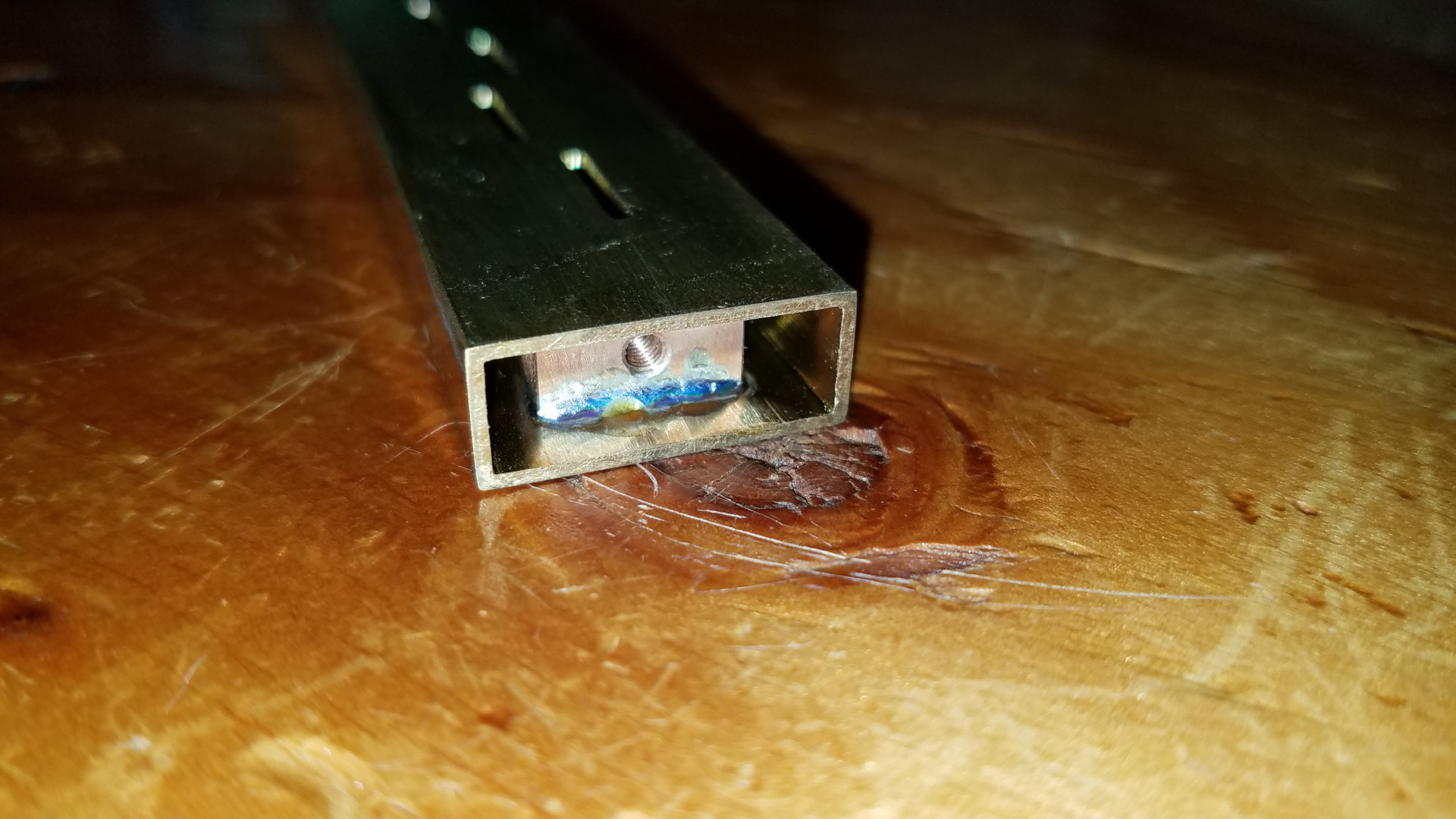
I never seem to take the shortest or quickest path to anywhere. I decided to put a beacon on the PARC/N1BUG repeater tower. Club members and leaders have been enthusiastic and very supportive. The beacon is a major expense and that slows down progress toward getting my home station 10 GHz capable but it will be eductional and helpful to me and perhaps others. Initially the beacon will be 10mW, 2x12 slot antenna and GPS locked. There may be a future upgrade path to 2 or 3 watts. Such an upgrade would have to be discussed with the club. I will consider that if the beacon would be of use to those outside the line of sight area.
I love it when a project finally comes together! The power and return loss meter is complete. All that remains is to send it out for calibration at 10368 (and perhaps 3400, 5760, 11000). Thanks to W1GHZ, W3IP, N8ZM and others for helping with this project.
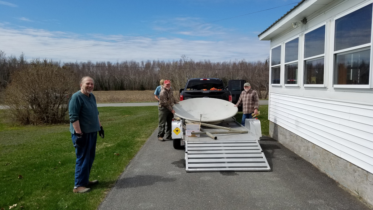
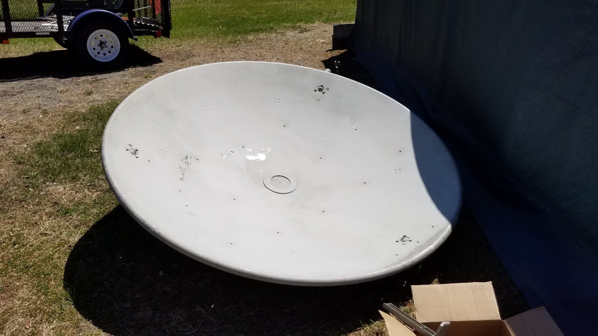
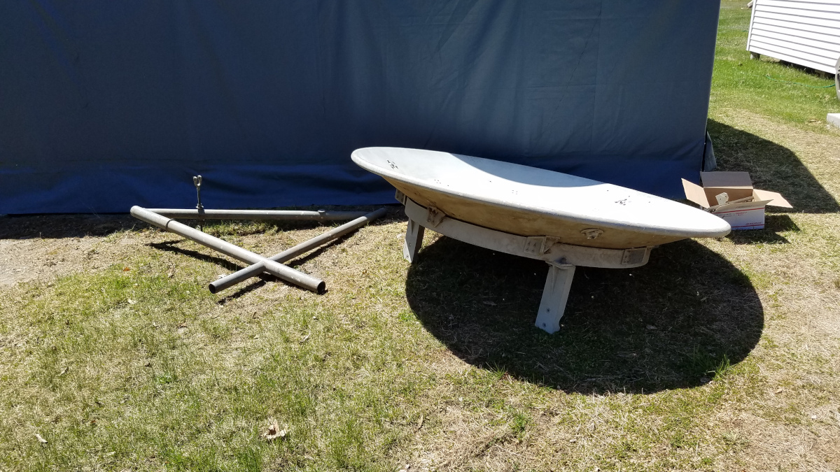
Barn find. With help from local hams I just dragged home this 6-foot dish found in a barn just five miles from my house as the crow flies. What are the odds of that in rural Maine? I have no idea what frequency this was designed for or how unkind years of storage and transport have been to it. But it was free so why not? I also got about 10 feet of WR90 waveguide with flanges I don't recognize. The rectngular flanges have eight holes but are significantly larger than the eight hole flanges on my other piece of WR90. There is also a few feet of what appears to be WR159. Thanks to NC1Y for the dish, KB1WEA, K2KJ and KB1WRZ for help with transport.

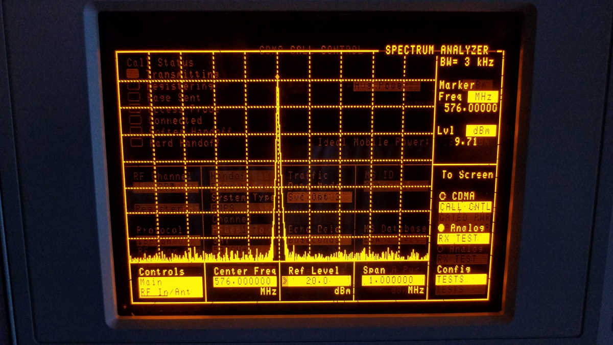
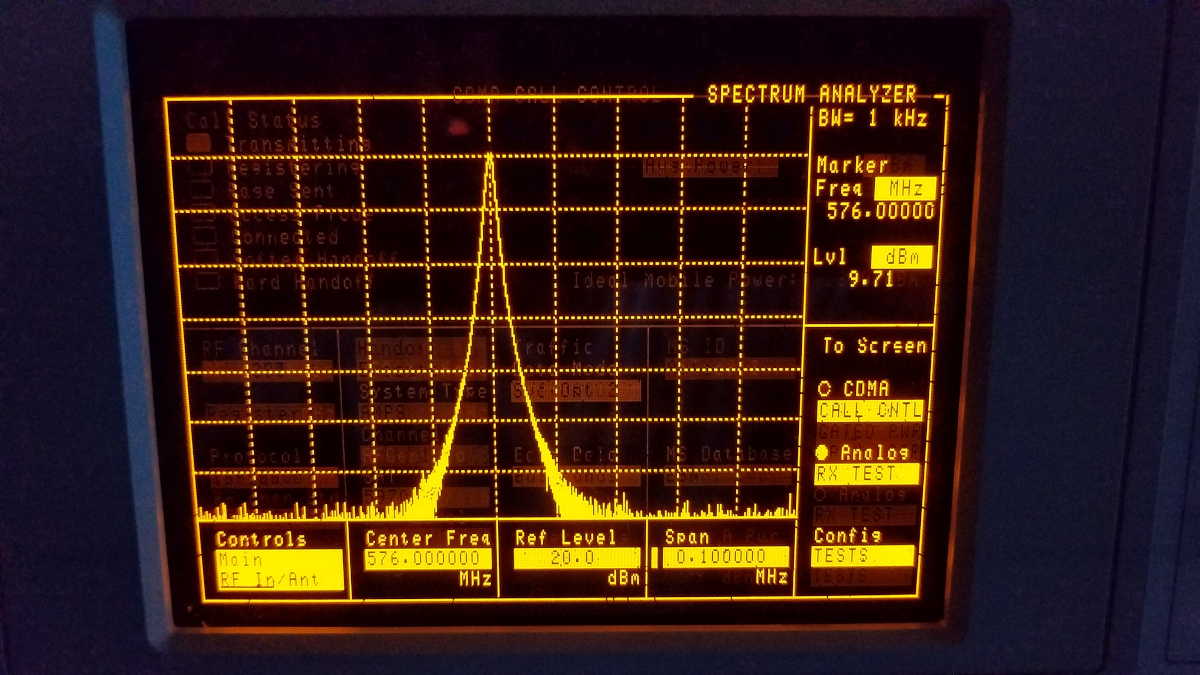
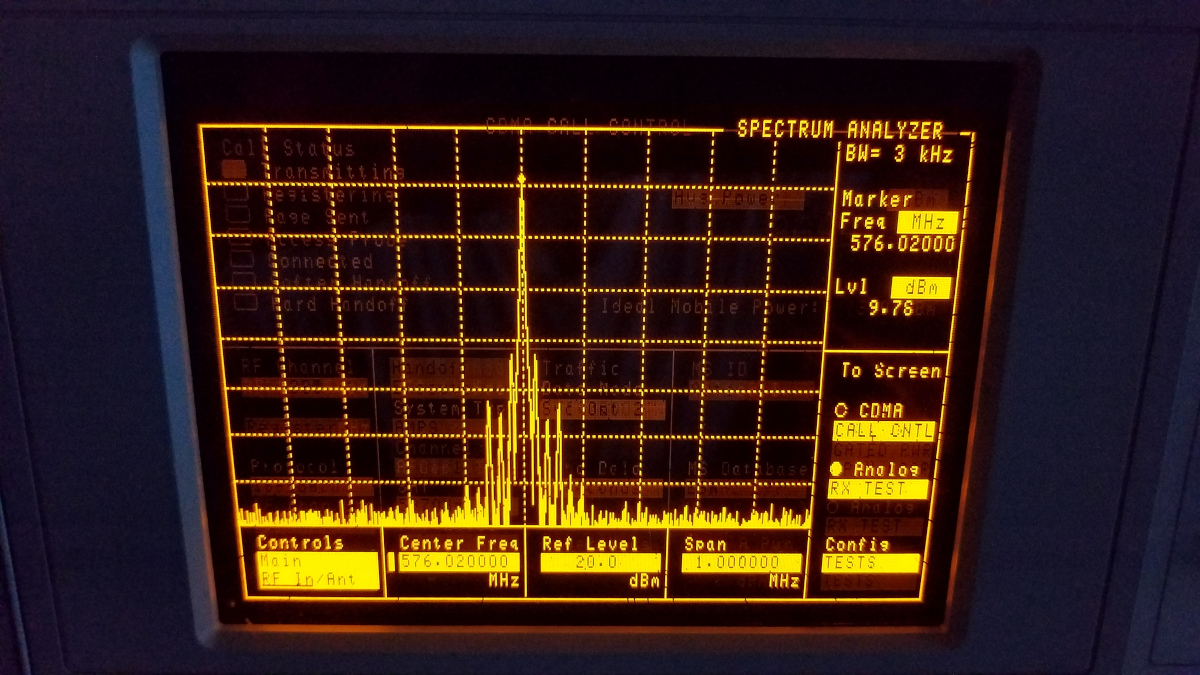
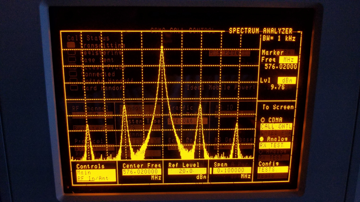
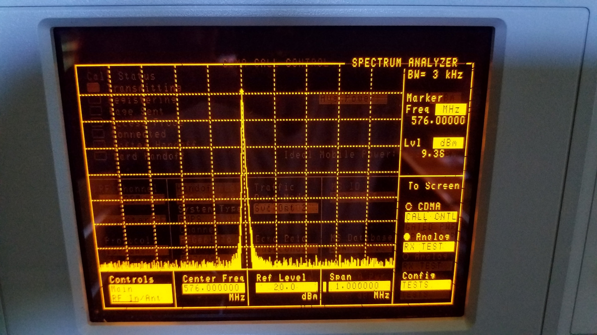
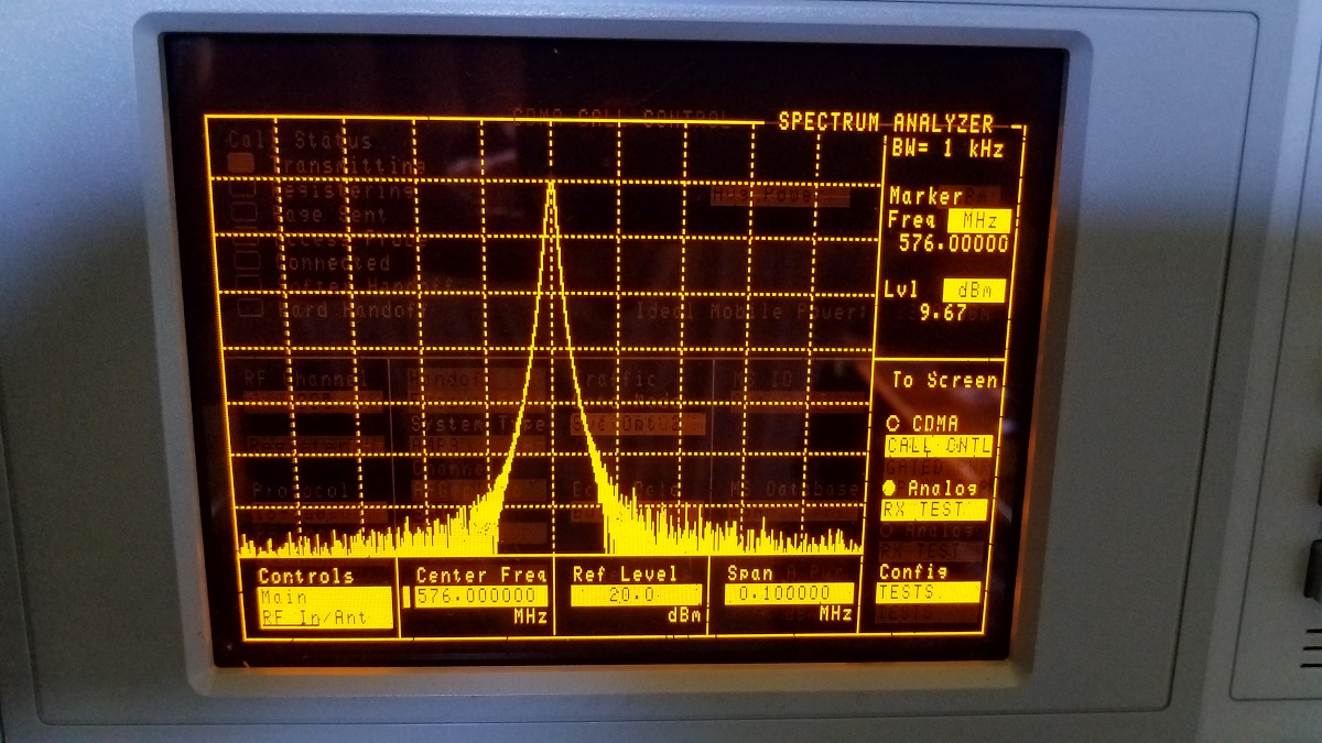
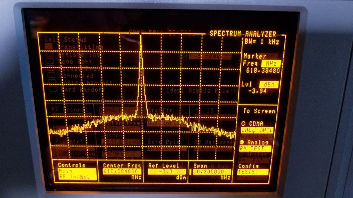
I ran into a snag on the beacon project. Having tried a VHF Design PLL module as a beacon exciter I did not like the hard, clicky keying. I decided to take a different approach using a W1GHZ Personal Beacon board. I believe I can get the keying on that to sound good. Since I had two Leo Bodnar GPS reference clocks laying around not serving any purpose, I decided to try using one at 576 MHz, into a doubler, then into the beacon board. Here is what I discovered. When progrmmed for 576000000 (10,368.000) the output of the Leo Bodnar is clean with no close in spurs. When programmed for any frequency that puts the beacon on a reasnable frequency it is not clean, having several strong spurs on either side. Here is an example programmed for 576020000 (10,368.360) showing spurs at +/- 20, 40, 60, 80 and 100 KHz. The first spurs are only down 33 dB. These would be on 10,368.000 and 10,368.720. I don't like that! The search is on for a signal source that can provide clean, GPS locked output at 576.020 or 1152.040. I cannot examine the latter with my spectrum analyzer directly but may be able to look at the final 10 GHz output using a satellite LNBF into my spectrum analyzer or SDR receiver.
Later in the day I decided to test the VHF Design board at the same two frequencies. I found no difference between the two frequencies. On both frequecies it looked reasonably good with a bit more "grass" on either side than the Bodnar. This may be phase noise or something else. I am not sure.


Just when I thought the only way I could tell anything about the spectrum of a beacon under test was to listen to it with a receiver, I was reminded one can use a satellite LNB into a 1 GHz spectrum analyzer to get a look at 10 GHz signals (thanks W1GHZ and W1FKF). I tried it today and while there may be some uncertainties it does work. There were too many reflections with the setup inside so I moved the signal source under test and LNB outside, with a cable running in to the spectrum analzer in its usual spot in the test equipment rack. I used the VHF Design PLL board that is built into my power meter as a test subject. I programmed it to generate 10,368.360 and looked at its radiated output spectrum using its internal TCXO, an external OCXO (I conveniently used the one in my microwave weak signal source) and with a Leo Bodnar GPSDO as the external reference. Ignoring slight frequency differences, the spectrum was virtually identical on all three, perhaps a couple dB lower phase noise with the GPSDO. Spurs were not a significant issue with the strongest ones being about 65 dB down. The plot shown here is with the GPSDO. I do not like the CW keying. There is a residual signal that is only about 45 dB down when "key up". Key clicks are also significant. Much work remains to be done building additional modules and testing possible beacon configurations to find the best one (that I can afford).
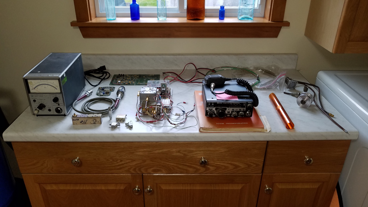
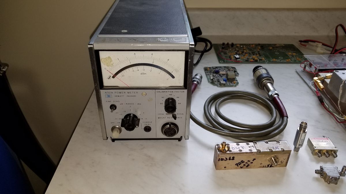
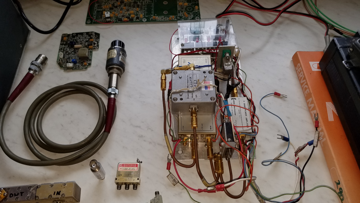
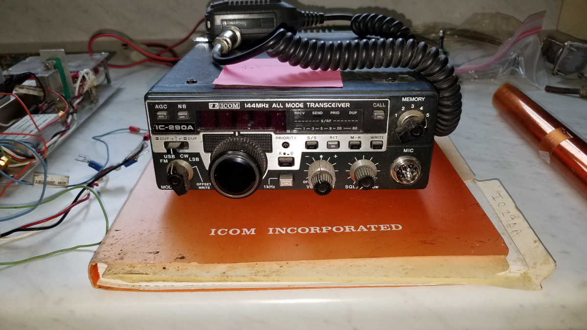
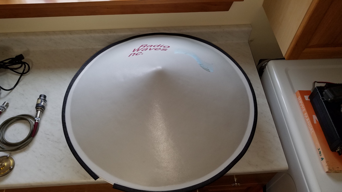
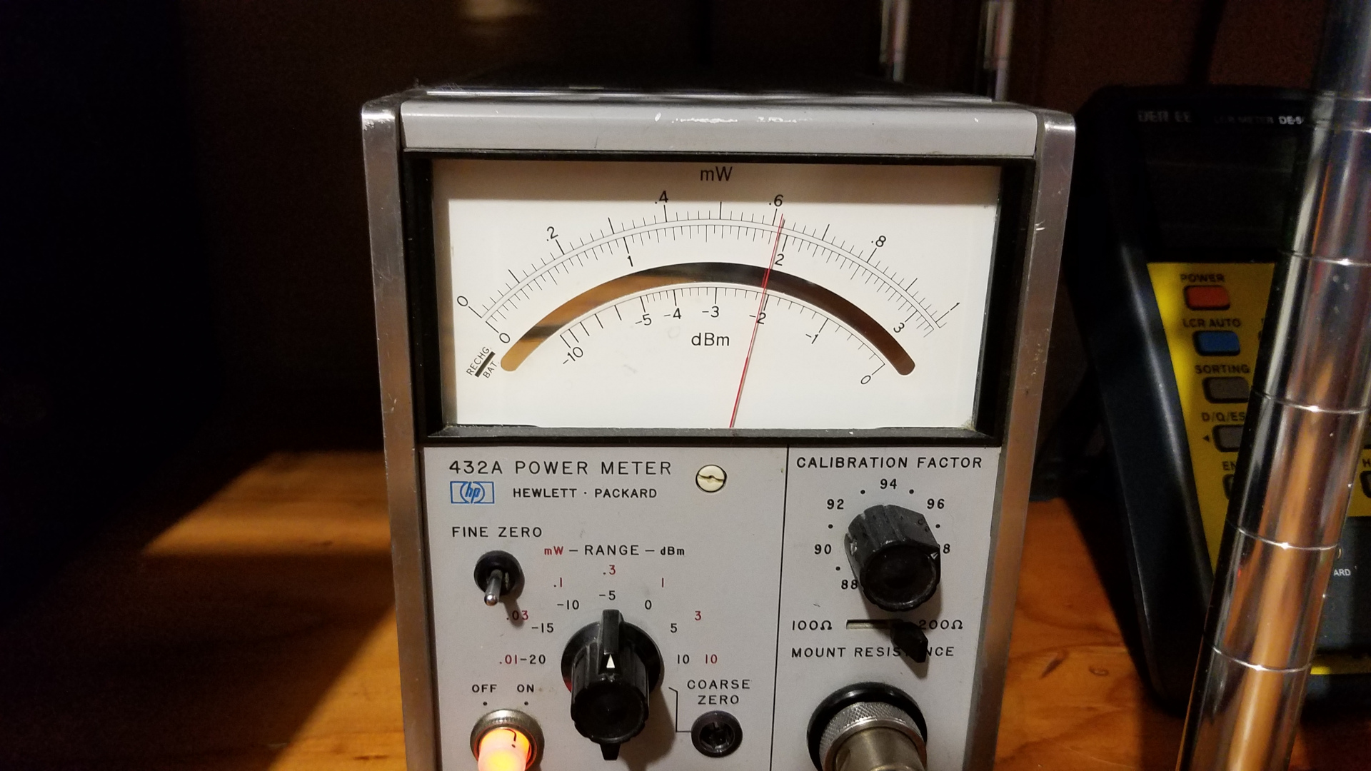
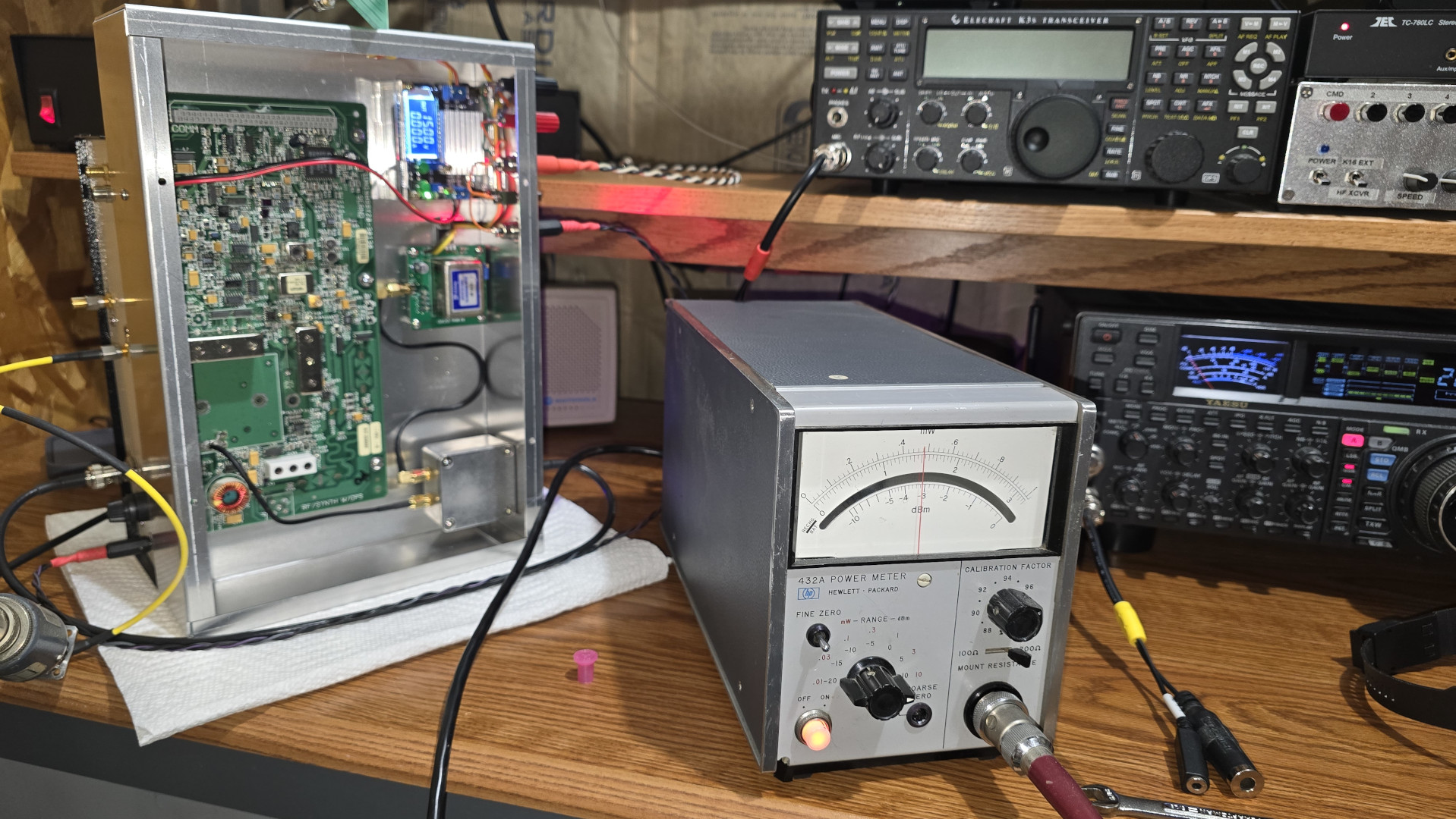
Christmas in June! Thanks to W1EX, W1FKF and W1GHZ for the pile of stuff W1FKF kindly brought to me yesterday. There is a HP 432A RF power meter with cable and 478A thermistor mount, a Kuhne 10 GHz transverter, a Kuhne 2 watt amplifier, DEMI preamp, T/R relay, an old Icom 290A 2 meter all mode transceiver which could serve as an IF radio if I were to get a chance to operate portable somewhere, various cables, a Radio Waves two foot dish with radome, a dish feed and many other small items. There were also several items for 1296 MHz not shown here. I am working on cleaning things and checking everything out.

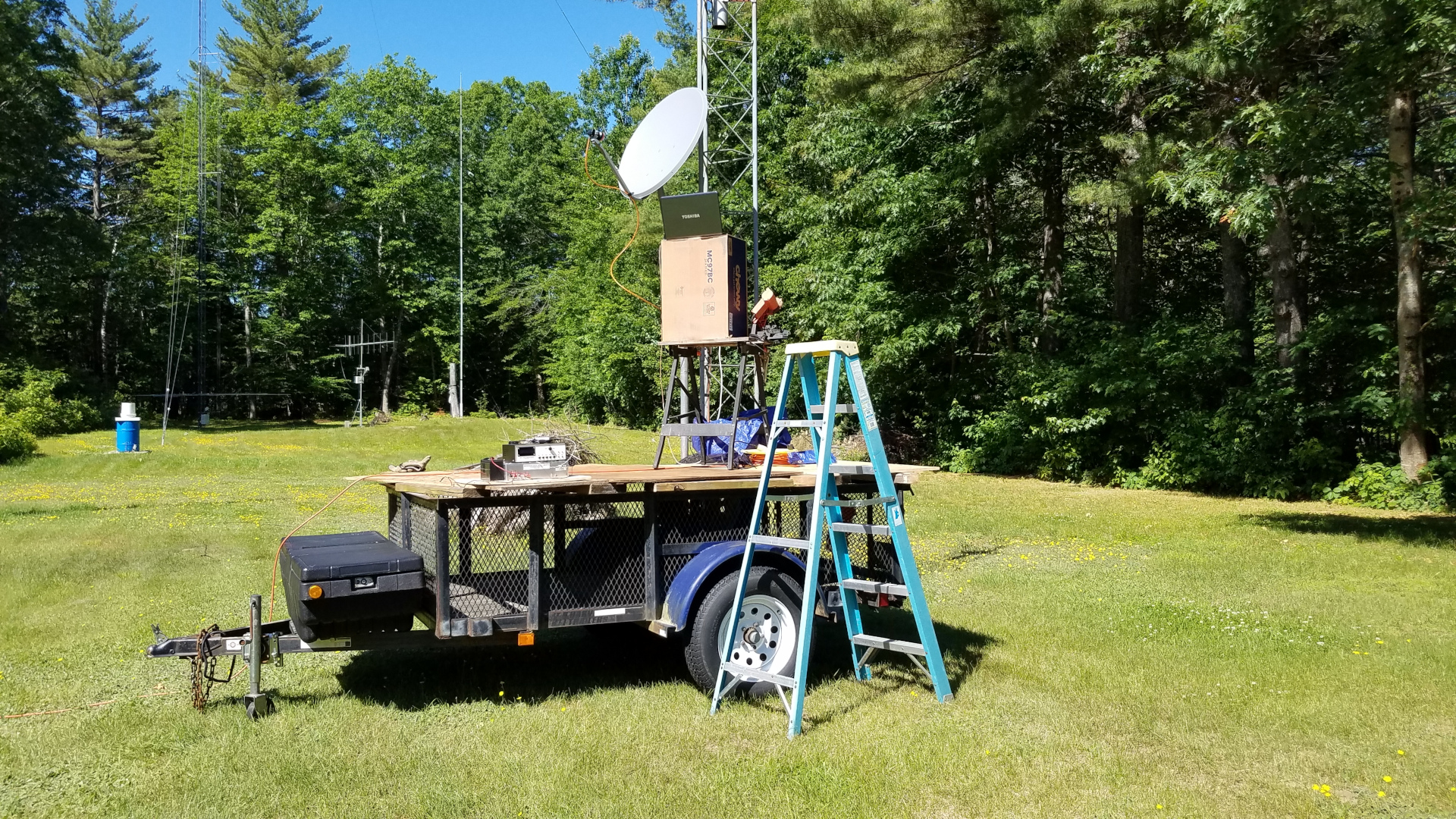
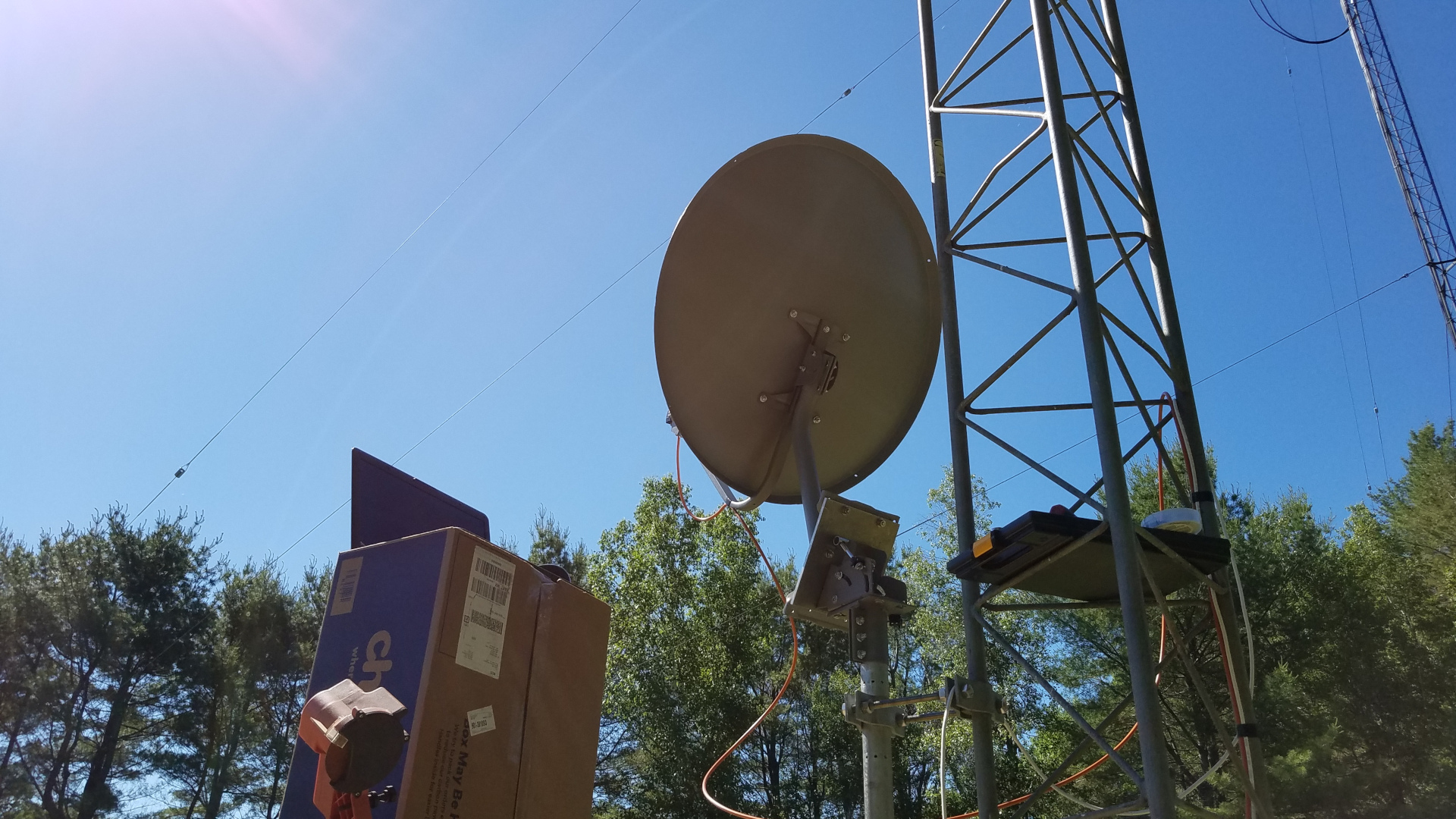
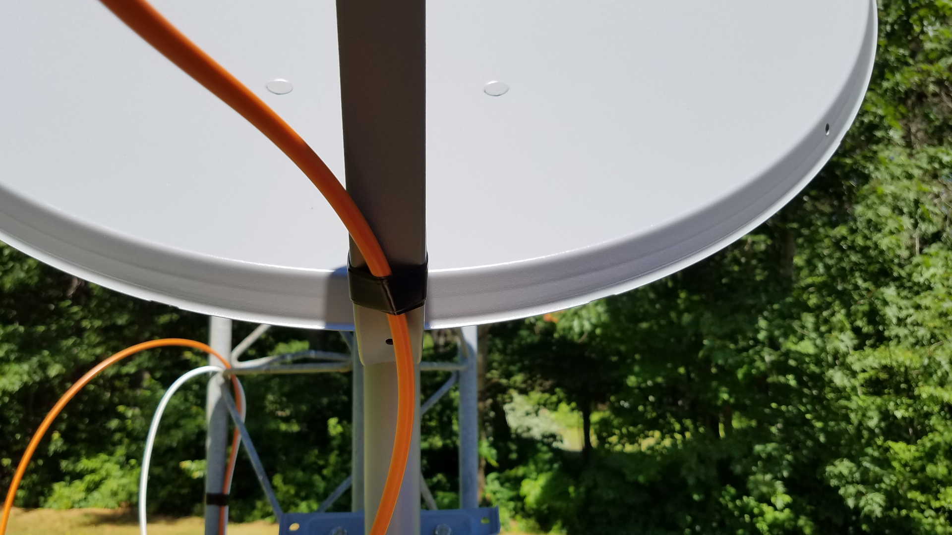
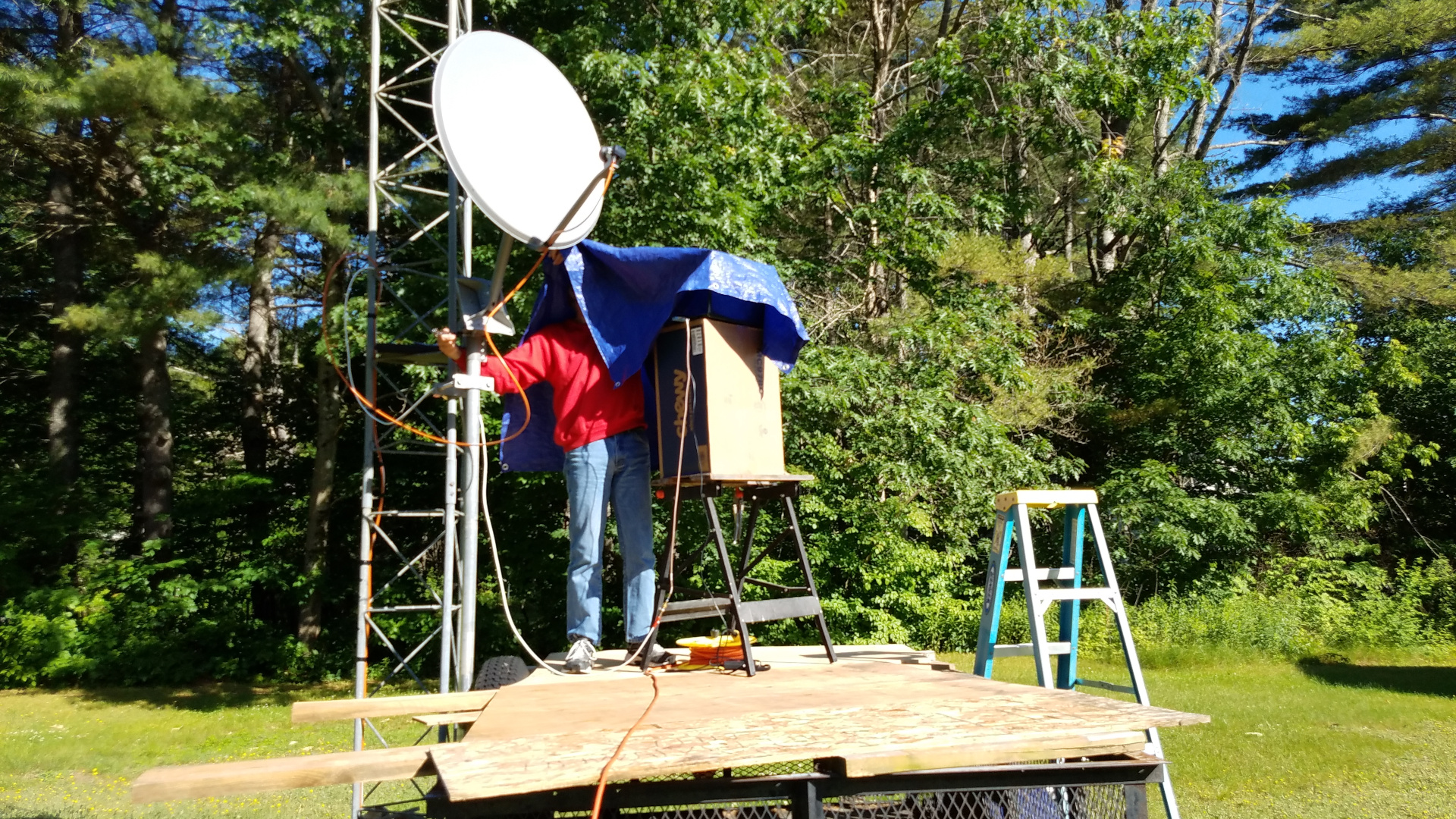
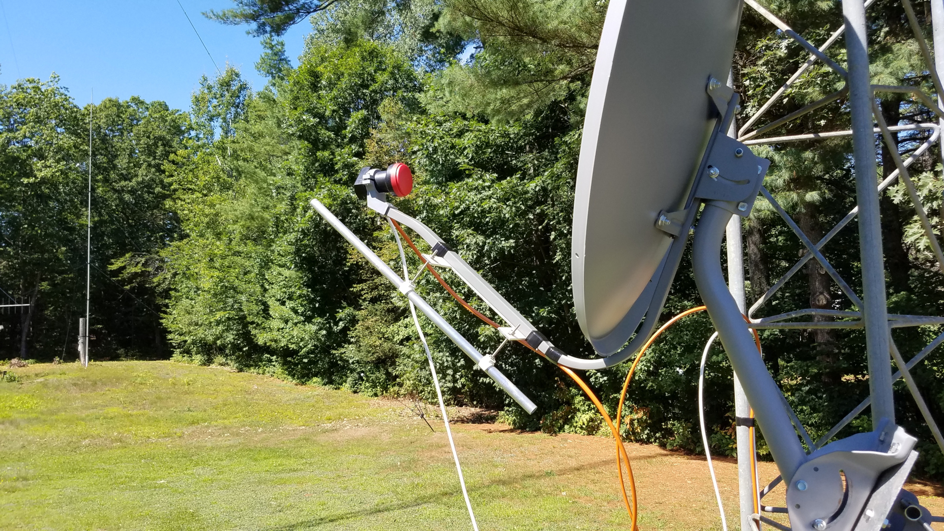
I got a Winegard DS-2076 76cm offset dish and a Bullseye 10 KHz LNB which I hope to use as a 10 GHz receiving setup. I wanted to play with the LNB position to try to optimize it, so I needed to set up the dish close to the ground where I could work with it to measure noise ratios: sky to sun and sky to ground. Since I have no budget for materials now, I needed to use whatever was on hand. The only sturdy mounts I have are my towers, so I decided to mount it to the side of my short Rohn 45 that is not being used. I clamped an 8 foot mast alongside. I did not want to cut that mast down as I will probably use it on a tower at some later date, but this meant the dish is about 9 feet off the ground - too high to reach. So I needed a work platform which was easily made with a utility trailer, some left over scraps of plywood and some dimensional lubmer that was laying around. Then I needed a platform for the laptop to bring it up to where I could see it while moving the dish. A small folding workbench and a cardboard box solved that problem. Finally I needed to be able to see the laptop display in the bright outdoor conditions. A tarp draped over the laptop and my head got the job done, though it was annoying to keep it on as I moved around doing things, and even the slightest breeze blew it away. At the top of the 8 foot mast I have a back assembly unit salvaged from an old, beat up DirecTV dish. The back assembly unit has fine adjustments for azimuth and elevation, so I can set a coarse position by hand and then fine tune it with the BAU. This worked well once I got used to it.
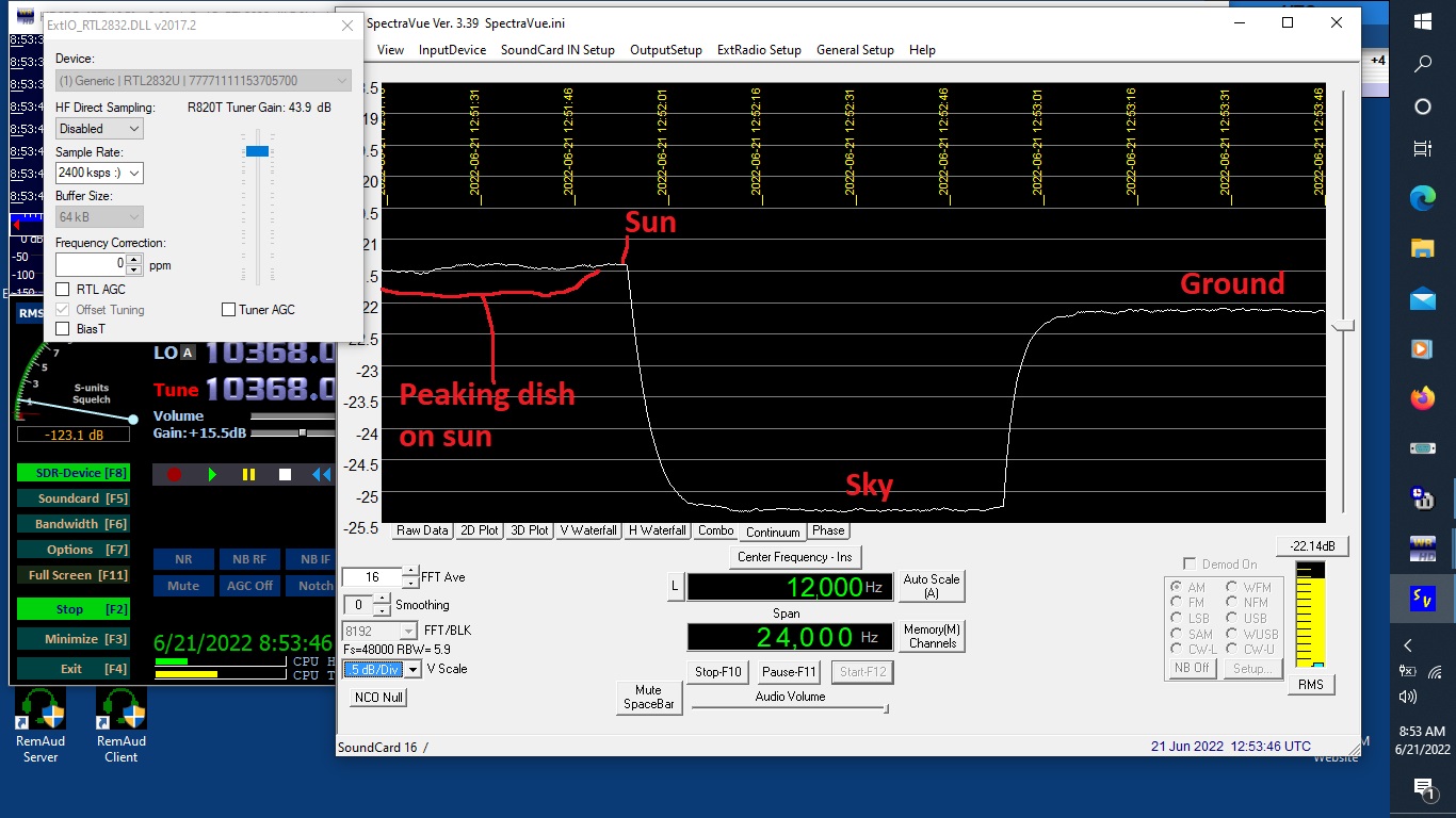
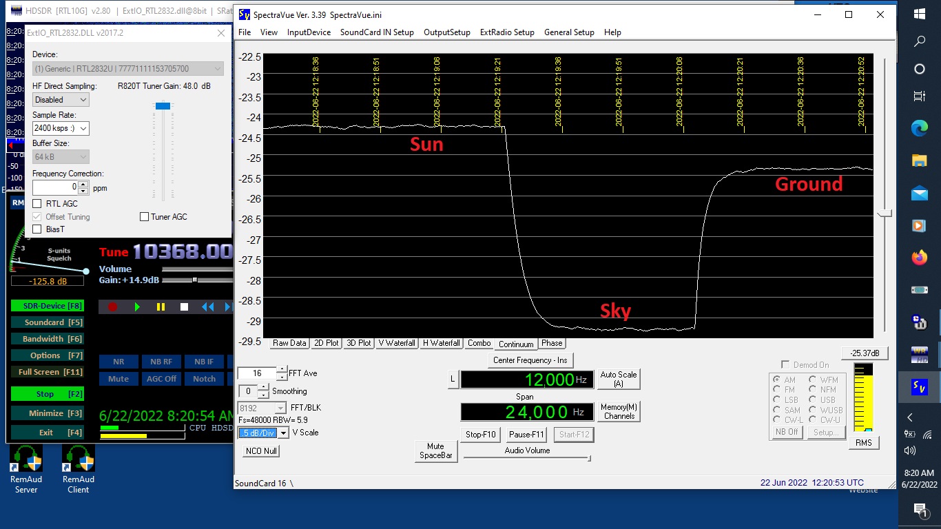
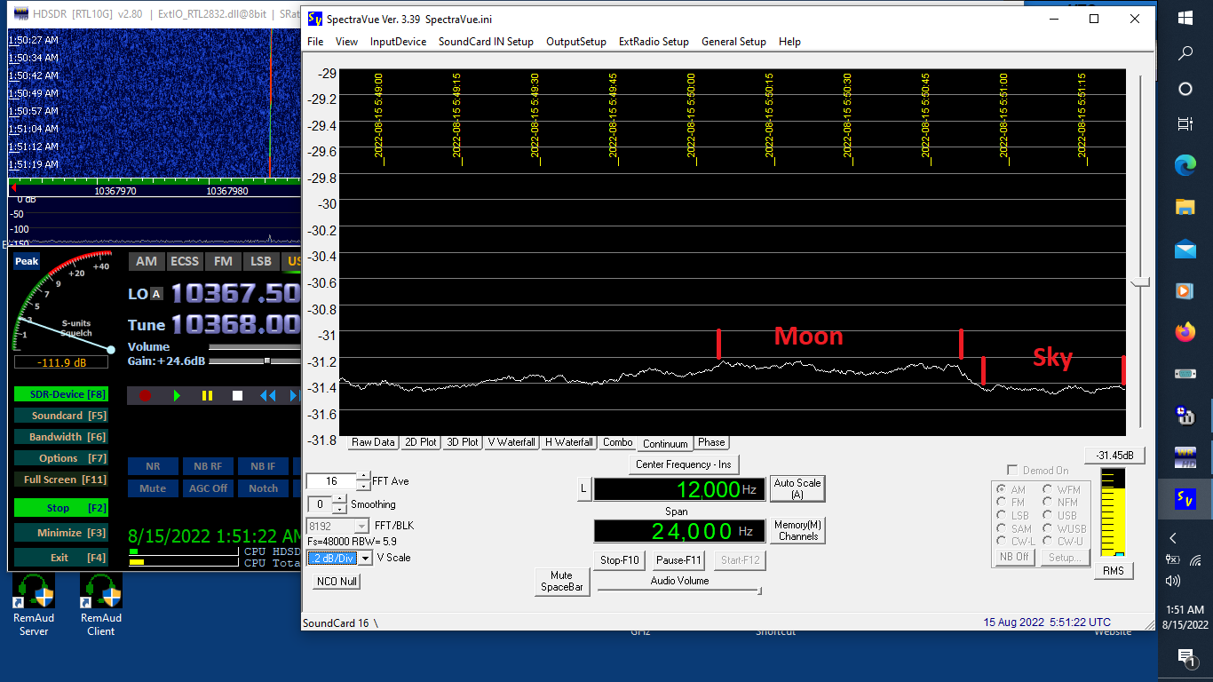
The LNB was feeding a RTL SDR with AGC disabled. I was using HDSDR and Spectravue, connected by VB Cable (a virtual audio cable). I saw only very minor differences in sun to sky and ground to sky Y factors as I moved the LNB in one centimeter steps. The best, by a slight margin, was with the LNB at its closest position to the dish. Here I measured approximately 3.9 dB sun to sky and 3.1 dB ground to sky. I am not certain how to interpret the measurements, but playing around with VK3UM's EMECalc a preliminary guess is that the LNB noise figure is around 2.5 dB and the dish is under illuminated. This is only a guess! There is a big variable in that EMECalc only seems to provide one feed that gives reasonabe efficiency for this dish and I haven't the slightest clue what that feed is! Opt dual-mode F2L x L3.10L means nothing to me. I do not know what type of feedhorn the LNB uses. Things are further confused by two different sets of numbers obtained from EMECalc at different times using input data that looked identical. I don't have a clue what happened there. When peaked on the sun, the LNB shadow was not as far onto the bottom edge of the dish as I expected, based on what I have read. Also it had a slight horizontal offset from bottom center.
More fun and games trying to verify and ajust this LNB and dish. Today I tried the LNB vertical probe instead of horizontal. There is a difference in the probe construction and at least some LNBs have better noise figure with the vertical probe. I found the Y factors were indeed better, with sky to ground showing 4.0 dB and sky to sun 5.0 dB. This still looks fishy to me and quite by accident I found a potential problem with my measurement setup. The first thing I did today was a control set of measurements to see if yesterday's result on horizontal polarization could be repeated. The Y factors came in about half a dB lower than yesterday. At the time I didn't understand this and went on to testing vertical polarization. Later I returned to look at horizontal again and noticed the level into Spectravue was a couple dB higher than yesterday and a few dB higher than today on vertical. The RTL SDR gain setting is very touchy, acting almost like an on/off toggle, but I managed to get it down a few dB. I was then able to replicate the results from yesterday. Now I question whether all of my results to date may be into a gain compression region for the RTL SDR and therefore not accurate measurements. Next time I will add an attenuator between the LNB and the RTL SDR and attempt to adjust the RTL SDR and HDSDR gain levels lower.

OK, I'm not sure what I know at this point! I went over the RX setup with my signal generator and calibrated gain to ensure that no stage was being run outside its linear range. I am confident I got that right. The biggest sky to ground and sky to sun Y factors seem to be with the LNB at its closest position to the dish and reamin near 4.0/5.0 dB. I might be getting some noise contribution from spillover when looking at sky. The dish can only see sky (or sun) to the east and southeast with elevation above 20 degrees or so. There are tall trees behind the dish to the west and northwest. I suspect these fill most or all of the spillover area and may be contributing noise when I am trying to measure sky. Whatever the case may be, this seems to be as good as it gets with this setup. Perhaps I could gain another tenth or two on the Y factors if I modified the LNB holder arrangement to get it even closer to the dish but I doubt that is worth the effort. Note: as of July 3 I have not had a chance to get back to this. I have been very busy with other things.

The PE1RKI 2x12 slot beacon antenna arrived!
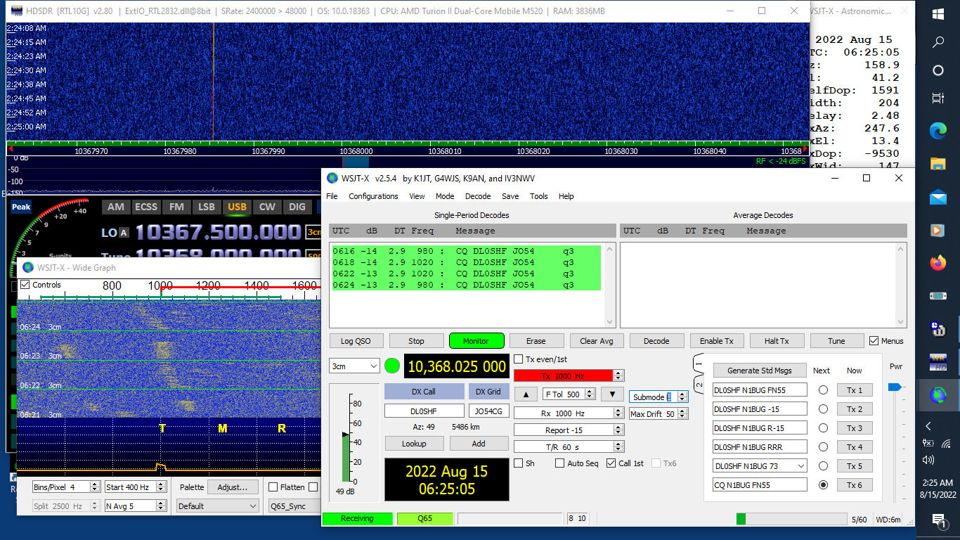
I heard my first 10 GHz signal - DL0SHF!!! I added a borsight to the dish and hastily constructed a work platform since the utility trailier is in use elsewhere. Last night I spent four hours standing on the platform trying to hear the DL0SHF EME beacon. I know for sure where the dish is pointing now, but there were a few challenges. It turns out on a night with a large, bright moon the boresight isn't needed. I can aim the dish by watching the position of the partial LNB shadow on the lower edge of the dish! Either the LNB or my old Nooelec RTL-SDR stick (the type with no TCXO) is prone to periods of drift. It will move two to three kilohertz in three or four minutes, then reverse direction and drift back to the starting point, more or less. During those times it was not possible to decode the Q65-60E transmissions from DL0SHF, but in between there were periods of relative stability where decodes were possible. It was a thrill to see the signal clearly on the waterfall and get the decodes! At first I wasn't sure in which direction to rotate the LNB to compensate for the roughly 55 degree spatial polarization offset, but that was easy to figure out -- rotate in the wrong direction and there is no signal! Another challenge was getting on frequency. I used my 10368 marker with the Qualcomm board to provide a reference, but it is not possible to calibrate out errors in the LNB LO and the RTL-SDR LO using HDSDR. I had to mentally calculate where to tune for the doppler shift (which changes very rapidly at 10 GHz!) and then subrtract whatever offset I had in the receive chain from that. Typically the latter was in the 14 to 17 kHz range. I was worried about this but it really wasn't all that difficult. Even with these challenges I was able to see the signal on the waterfall within five minutes. The first decode was about 15 minutes after that as the LNB warmed up and its drift slowed down. I did have to recalculate the frequency and retune often due to receiver drift and doppler shift.


I tried to compare my three LNBs by looking at sky to ground noise Y factor. This is dicey at best, as I have a very limited view of the sky. I did my best to make sure all three LNBs were pointed exactly the same when looking at sky and ground, but there may be differences in beamwidth of the LNBs and I cannot be certain they weren't seeing the tops of some trees. These tests should not be taken too seriously, but it appears any noise figure differences between the LNBs is relatively minor? The first is the Avenger KSC 321S-2 LNB. The second is the Bullseye 10 kHz LNB I have been using for previous tests, including EME reception. The third is another Bullseye 10 kHz LNB I recently obtained as a guinea pig for hacking.


As noted in my comments about EME reception, drift is a problem with the Bullseye 10 kHz LNB. My old non-TCXO RTL-SDR stick was likely contributing to the problem as well. Last week I attempted to modify the Avenger KSC 321S-2 LNB to use an external LO following KA1GT's notes. I was successful in destroying an Avenger when two very fine PCB traces ripped off the board during my attempt to remove the crystal! Oops. OK, moving on then. I was curious to see if it would be possible to use an external LO with a Bullseye 10 KHz LNB. These have the second type F connector for internal LO monitoring. The TCXO output passes through an attenuator to this connector. Would it be possible to feed an external LO into this connector without further modification after removing the TCXO? Would the LNB lock to 25.476923 MHz to get a 432 MHz IF?
The Bullseye was easier to disasseble than the Avenger. On the former I had broken several of the little clips holding the two halves of the plastic case together prying it apart. On the Bullseye I was able to reach inside through the oval cutout around the connectors with a small screwdriver and pry open four of the six clips while squeezing the sides of the top half of the case. It came apart with no broken clips. A bigger challenge is the white silicone sealant around the perimeter of the metal case and edges of the PCB. Removing that required careful cutting with a knife and lots of picking at it. It is necessary to be gentle about prying the PCB loose, as it may be easily damaged. The TCXO output is a sine wave. Using an oscilloscope I measured the voltage at the TCXO oputput pin at approximately 700 mV peak to peak. The heavily attenuated level at the red F connector was much less. My attempt at removal of the TCXO with the little PCB still in the metal case was not successful. Apparently there is fairly good thermal transfer from the PCB to the case. My hot air station was not able to overcome that to melt the solder. Only the two F connector center pins need to be unsoldered to remove the PCB. I was able to do that with my soldering iron and solder wick. Once the board was out, hot air easily removed the tiny TCXO.
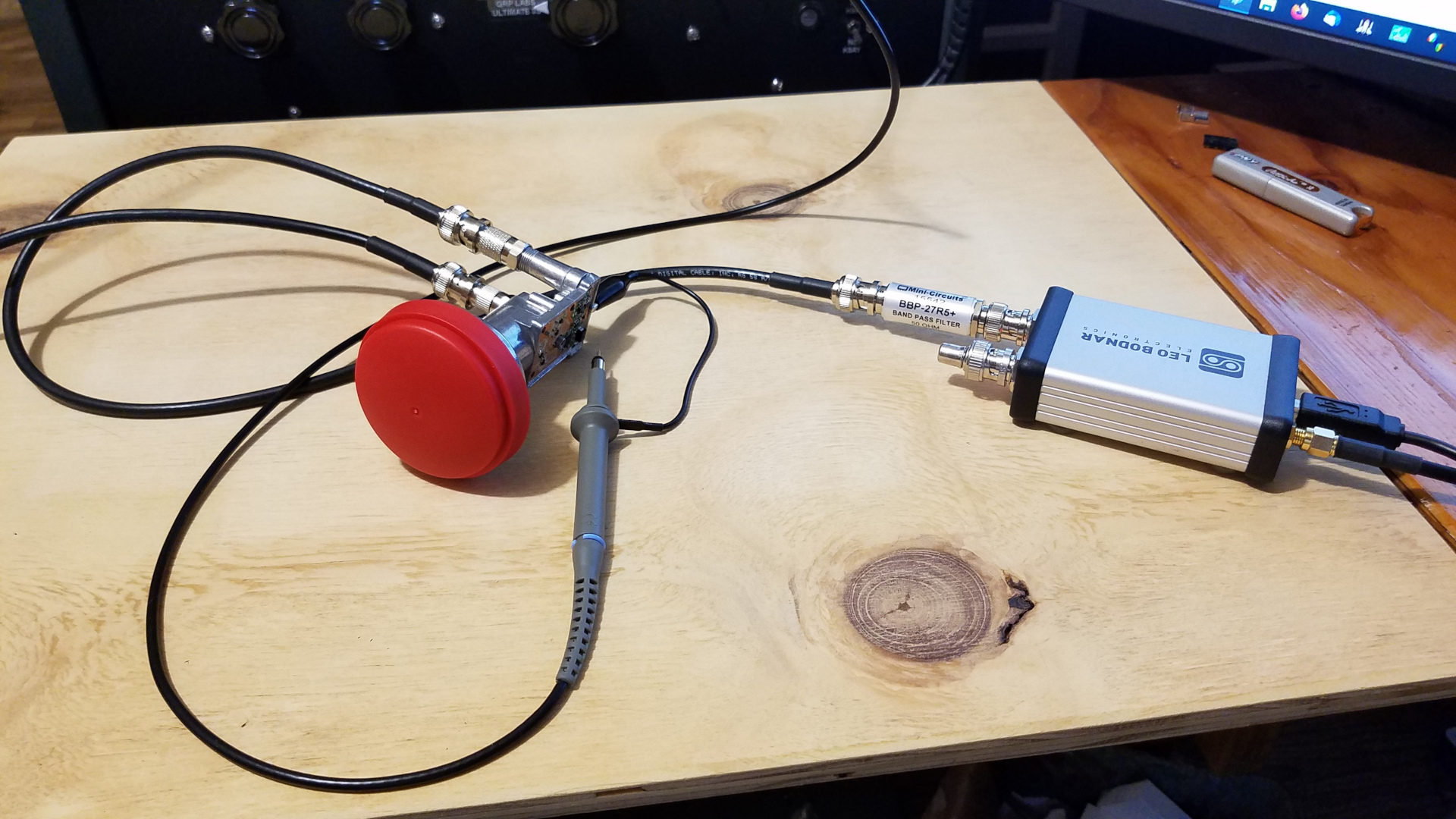
I tried injecting 25,000,000 (for 618 MHz IF) and 25,476,923 (for 432 MHz IF) from a Leo Bodnar GPS reference clock, but the Bullseye did not lock to it. The Bodnar output is square wave but the waveform at the old TCXO output pad was a mess, neither square nor sine wave. It had multiple peaks and looked more like 2fo than fo. The peak to peak level was only about 300 mV. I didn't know if failure to lock was due to the waveform, insufficient level, or both. Next I put a Mini-Circuits BBP-27R5+ band pass filter on the output of the Bodnar. This is a 24 to 31 MHz filter, resulting in a nice looking sine wave. I now saw a clean sine wave at approximately 300 mV peak to peak at the old TCXO output pad. The Bullseye had no problem locking to this at 25,000,000 or 25,476,923. Up to this point I had been running the Bodnar at its maximum output level with drive set to 32 mA. I found that I could reduce it all the way to the lowest drive setting of 8 mA and the LNB remained locked. Progress! I connected the LNB to my Q5 Signal 432 transverter and switched on my 10,368 weak signal source. I had a nice strong signal about 180 Hz above 432.000. The small error is most likely the transverter, which is using its internal TCXO. (Note: 25,476,923 Hz times 390 comes out to 9935.999970 MHz, or 30 Hz below target. This is the best we can dp with 1 Hz steps on the Bodnar. During a two hour observing period there was less than 20 Hz drift. It appears the Bullseye LNB can be locked to an external LO via the red F connector with no modification other than removing its internal TCXO. Great! There is some phase noise evident and a spur only 20 dB down about 60 Hz below the fundamental. Further investigation is warranted but for weak signal work such as EME I don't think this will be a problem. With a signal about 35 dB above the noise floor, phase noise did not appear to present any problem for receiving signals a few kHz removed from the moderately strong one. I did look at the Bodnar output spectrum around 25.476923 on the spectrum analyzer and found it to be clean (but that spur at only 60 Hz removed is too close for me to see if it is present). I should have taken photos of the waveforms and levels noted above, but didn't. I was too interested to get on with the work and see the results. Sorry about that!

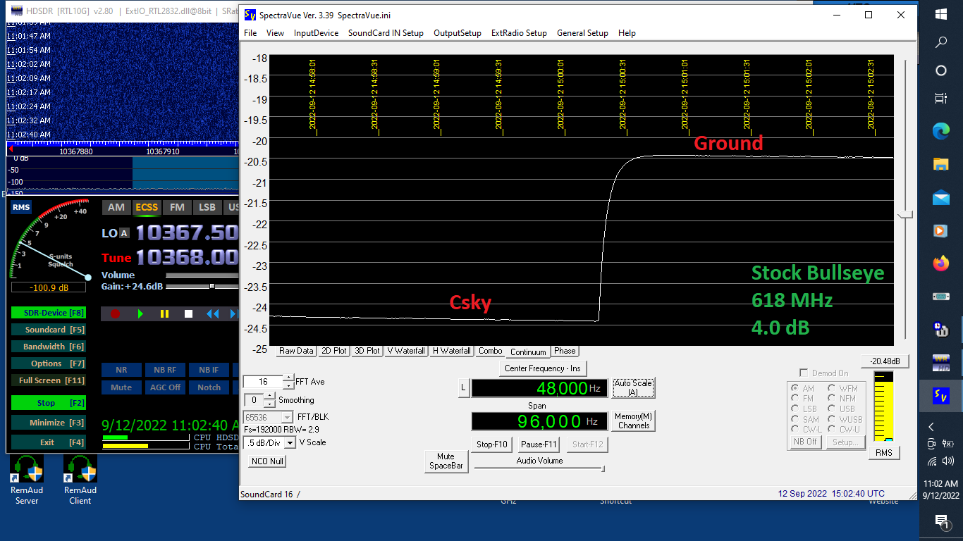
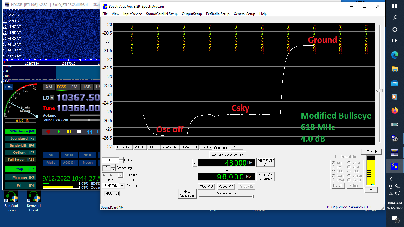
As noted in the last post, I ran into some problems getting the LNBs to work with 432 MHz IF. I realized something was wrong when I checked the DL0SHF beacon and found SNR to be 5 dB lower than it had been with the stock LNB. Both the Bullseye and Avenger LNBs do work when moved to 432 IF, but performance suffers. They still have plenty of gain and definitely receive signals, but noise figure takes a dive. The follwing Cold sky to ground noise plots show the problem. Less difference between cold sky and ground means poorer performance. The good news is performance at 618 MHz IF remains the same after modification. So they can be stabilized using a GPSDO or other accurate external reference, and the reference level does not seem to affect performance as long as it is enough for the chip to lock to.
First the Bullseye 10 kHz LNB (BE01):

And now the Avenger KSC321S-2 LNB:

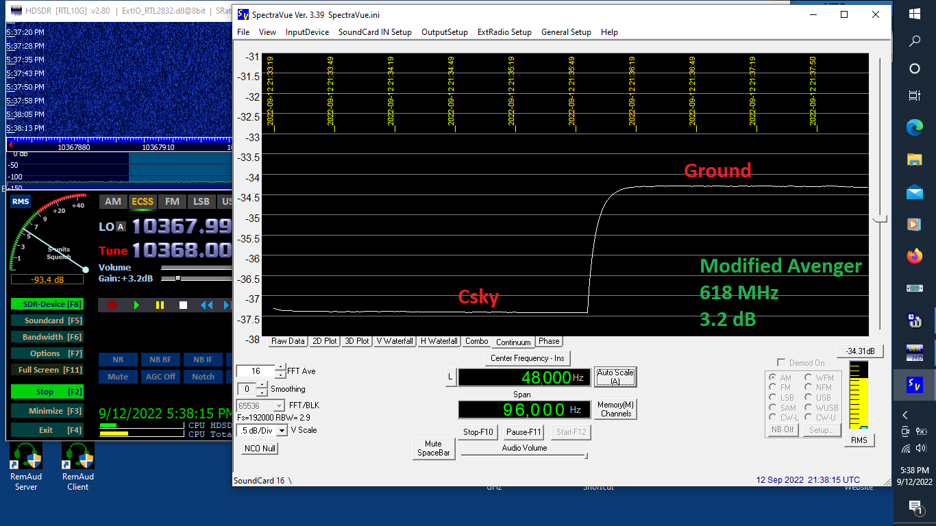

The Bullseye appears to have a lower noise figure than the Avenger, both stock and modified as long as the IF remains 618 MHz. It is also far easier to modify for external reference, making it the preferred choice in my opinion. Interestingly the Bullseye suffers a much greater performance reduction when moved to 432 IF than does the Avenger, but neither LNB is happy there.
Is there any hope for improving performance of the Bullseye LNB at 10.368 GHz? Possibly. I did a quick check at 10.968 GHz to 1218 MHz using the nominal 25.000 reference frequency. The cold sky to ground Y factor improved 0.5 dB over the 10.368 to 618 using the same reference. Bear in mind this is with the LNB on my 76cm dish. The dish should have about half a dB more gain at this frequency. I have not tried to work out the calculations to see whether this improvement in cold sky to ground Y factor is all due to more gain or partly due to better performance / lower noise figure of the LNB. Adding a tuning screw opposite the vertical probe in the Bullseye might offer some improvement at 10.368. An experiment for another day!

I had been digging around the internet off and on for weeks looking for some way to implement WSJT-X doppler tracking with HDSDR and my RTL-SDR dongle. I had
found a couple of methods that were quite complex and required installing more software. This was one reason I wanted to use 432 MHz IF, so that ultimately the
receiver would be my FT-2000 which is easy to control directly from WSJT-X. The other reason had to do with not liking SDR for extreme weak signal CW copy.
Eventually small hints here and there come together in my foggy head and I realized it should be possible to control HDSDR directly from WSJT-X if I had a
connected pair of virtual COM ports. Having prior experience with VSPE from my 2200 meter days, I chose it to create a pair of virtual COM ports. Configuration was
easy.
First, start VSPE and create a pair of virtual ports:
Click create new device.
Select Pair for device type, then click Next.
Choose any two available COM ports. Leave emulate baud rate unchecked. Click Finish.
Configure HDSDR:
Options>CAT to HDSDR>Port, select either of the two virtual ports of the VSPE pair.
Options>CAT to HDSDR>baud rate, make a selection (I chose 9600).
Options>CAT to HDSDR>activated, just click on it.
Configure WSJT-X:
File>Settings, Radio tab.
Choose Kenwood TS-2000 for radio type. This is the command set HDSDR understands.
Choose the other COM port of the virtual pair.
Select the same baud rate you chose in HDSDR. Ohter port options can be left at Default.
Select Fake It for the split option. Although not used to control HDSDR, this is required by WSJT-X.
That's all there is to it. Open the WSJT-X Astronomical data window, click the box for doppler tracking, and select the type of doppler compensation you want.
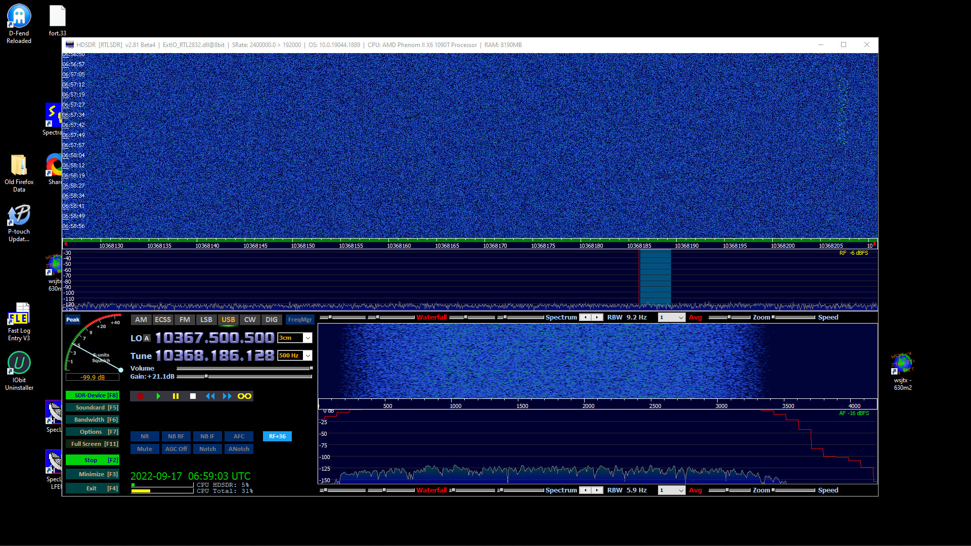
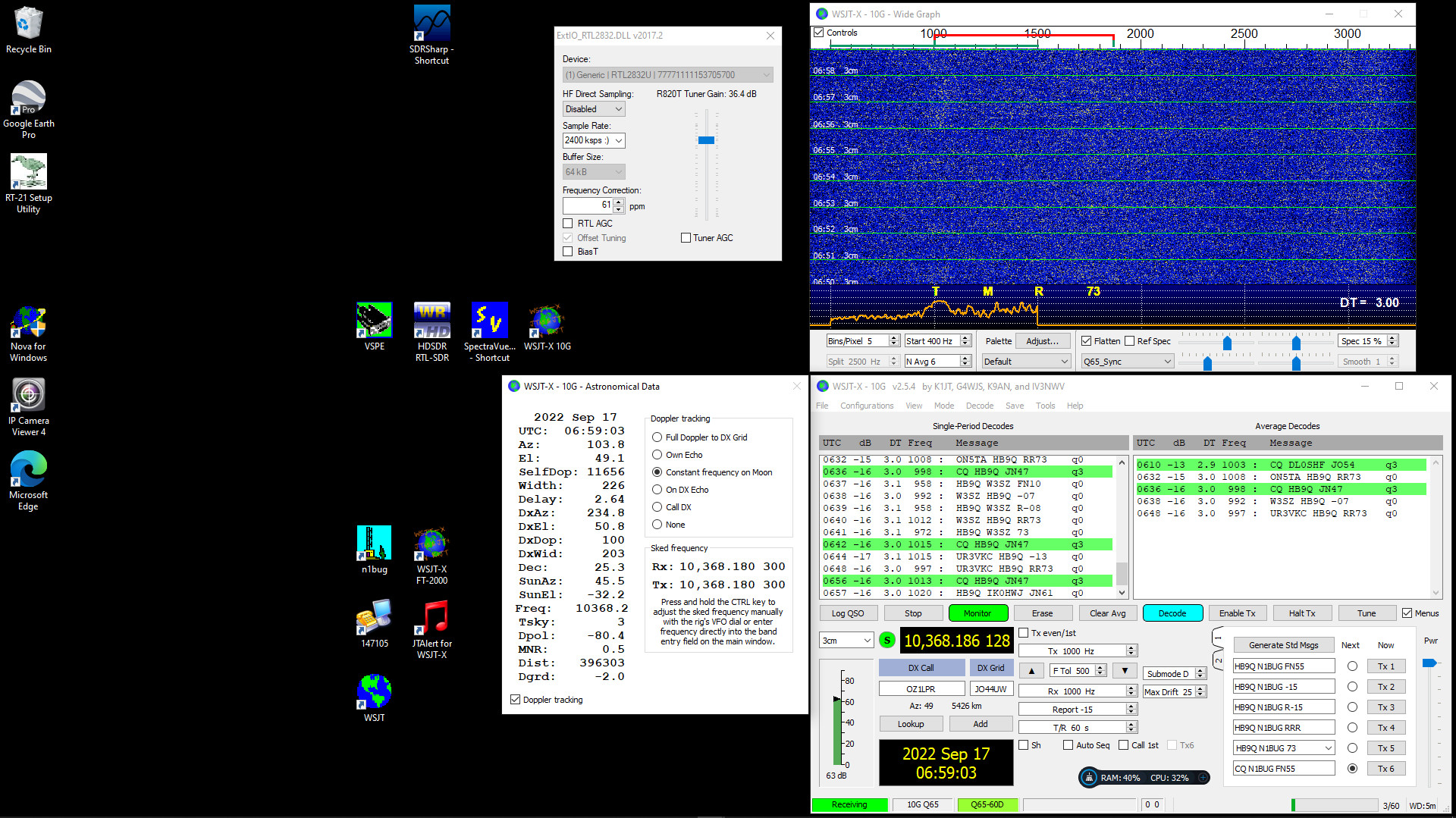
It should just work at this point. Receiving EME signals is much easier with a GPS referenced LNB and automatic doppler tracking! Compare the nice straight line
on the waterfall with the one from August 15.
I had clear skies for locating the moon on Friday night, which happened to coincide with one of the ARRL EME Contest microwave weekends. I was able to decode the DL0SHF beacon at -12, W3SZ -16, GB2FRA -8, IK0HWJ -16, HB9Q -15, and OZ1LPR -15. It was very gratifying to see that my simple LNB based setup is capable of receiving a number of stations on EME! GB2FRA had a really nice signal and was clearly visible on the HDSDR waterfalls.
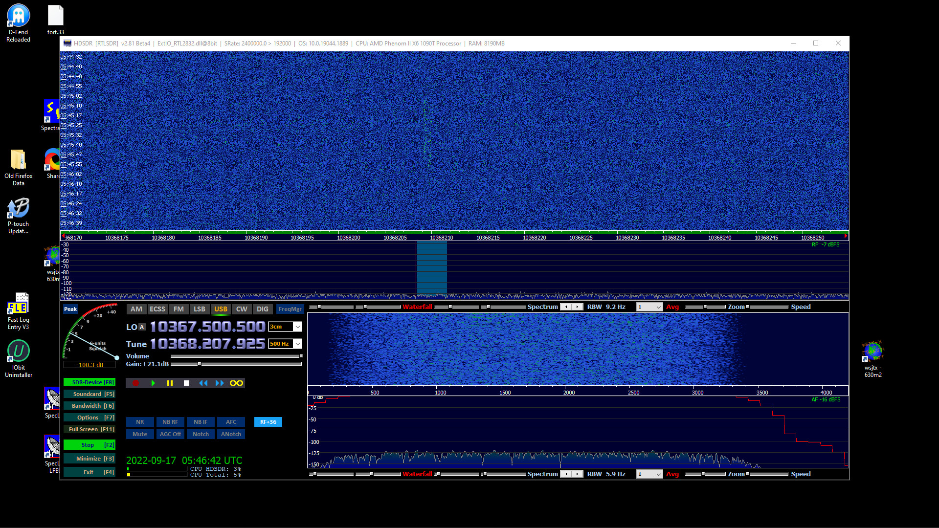
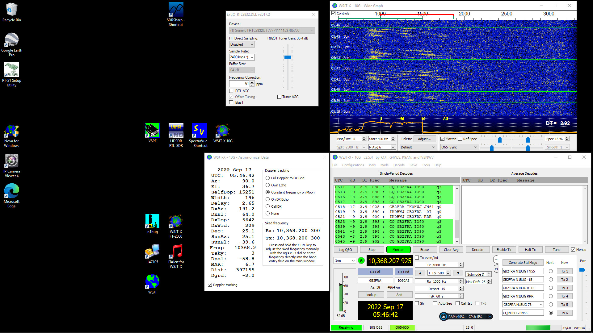
Right at the end of my moon window, GB2FRA was working DB6NT on CW. I knew I didn't have time to switch to CW mode in HDSDR and adjust filters to get optimum copy and the dish needed to be moved so I did the best I could in SSB mode. I am very disappointed by having to use SDR as they are so awkward for me to adjust for very weak signal copy by ear. A conventional receiver would have made this so much easier. I was able to "easily" copy both call signs, RRR, TNX, and 73 but I never really copied the signal report during the QSO. Here are some sound clips:
Early in the QSO, 800 Hz pitch (not good for my ears!)
Later, 500 Hz pitch (ah, that is better!)
I was getting a lot of questions about the EME RX setup so I made a Youtube video wherein I describe it in some detail. One thing I did forget to mention in the video is polarization. I rotate the LNB in the clamp to set the correct polarization for the station I am listening for. Europe mostly transmits vertical, and I am using the vertical probe in the LNB because it has lower noise figure than horizontal. So for Europe I simply rotate the LNB the specified number of degrees for the Dpol given by WSJT-X. A negative Dpol means rotate the LNB counter-clockwise as would be seen looking from the dish surface or behind the dish. It's slightly more confusing with North American stations who usually transmit using horizontal polarization. First I rotate the LNB 90 degrees to get horizontal plolariztion, then rotate it according to the given Dpol figure from there. Clear as mud?
I did some testing of possible exciters for the beacon. As discussed last year (see above), the Leo Bodnar GPS reference clock has strong close-in spurs. I won't put that on the air. See my Leo Bodar test video for more details. The VHF Design PLL board does OK but has relatively strong phase noise and cannot produce all desired frequencies exactly. See the VHF Design test video for more. I bought a custom programmed DigiLO from Q5 Signal. Corey kindly added all the frequencies it is capable of doing that would put a beacon in the 10,368.3 to 10,368.4 range. The DigiLO can produce a clean signal at 1152.000000 which would end up at 10,368.000 after x9 multiplication, but when set to produce any frequency in the typical beacon segment it has some close in spurs. They are not as bad as the Leo Bodnar but I wanted to see if it could do better wtih another technique. It turns out the spurs can be eliminated by setting up the DigiLO for 1152.000 and using the Leo Bodnar GPS reference clock to supply a modified 10 MHz reference. 10.000299 will put the final result on 10,368.310 exactly. Phase noise with the DigiLO is lower than the VHF Design. Here is my DigiLO test video with the details.
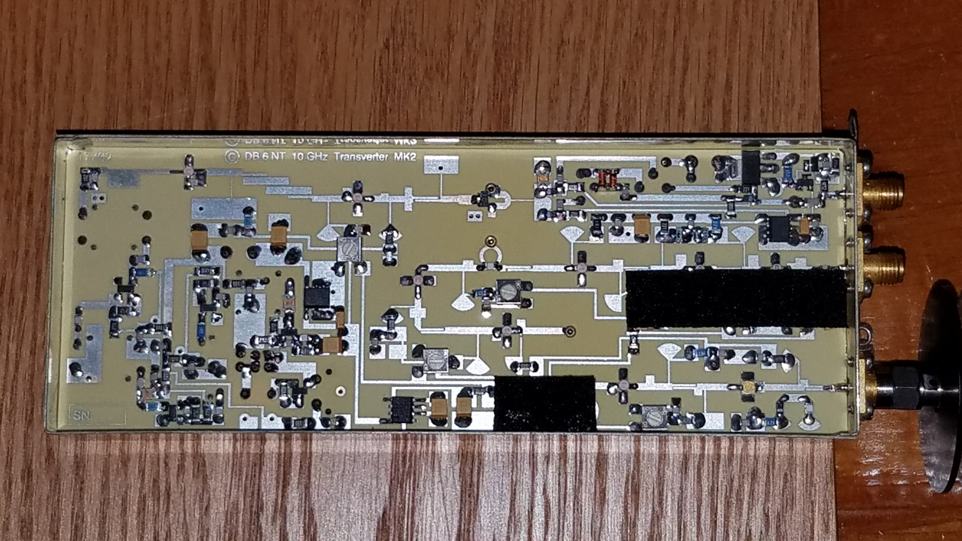
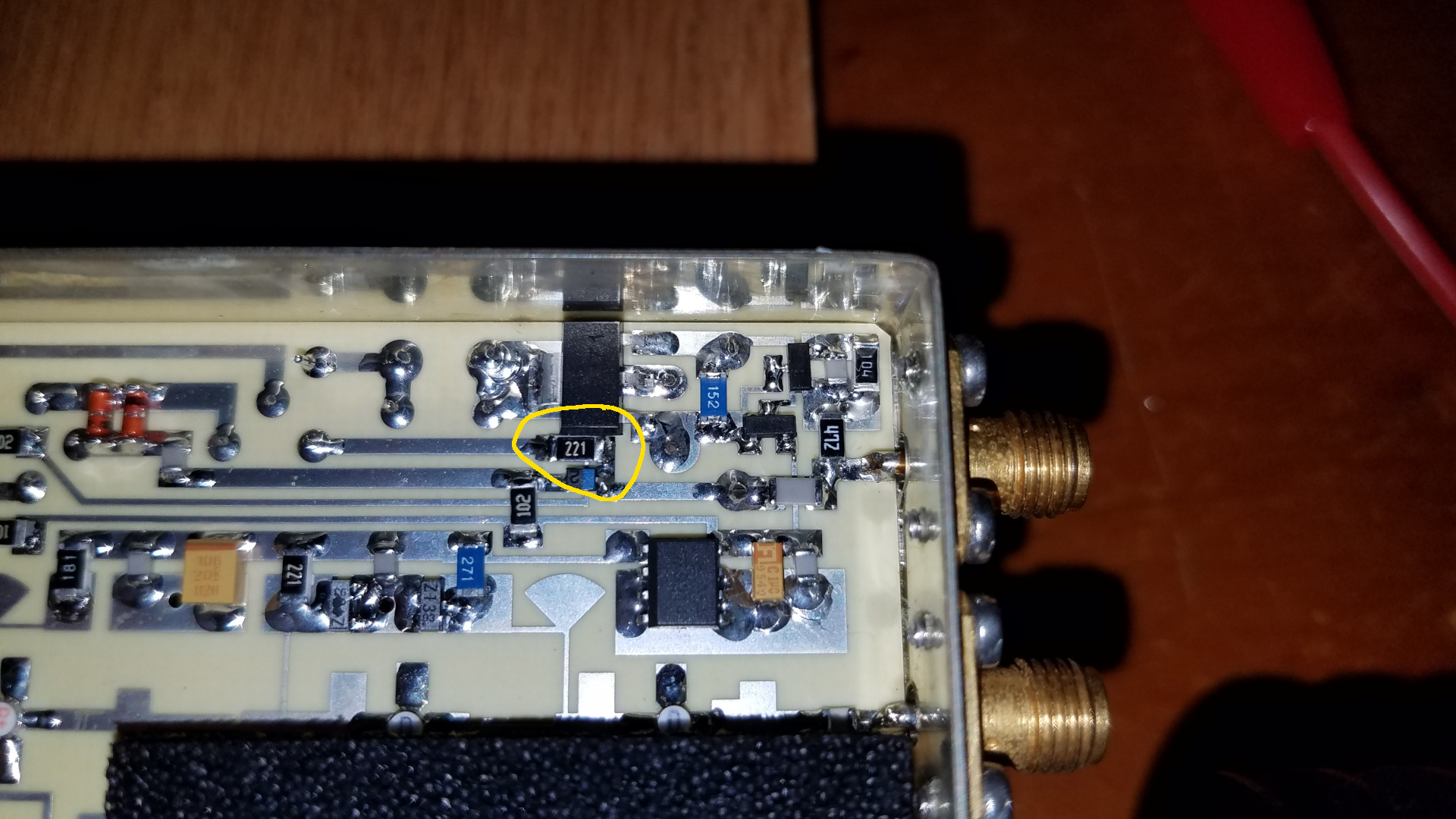
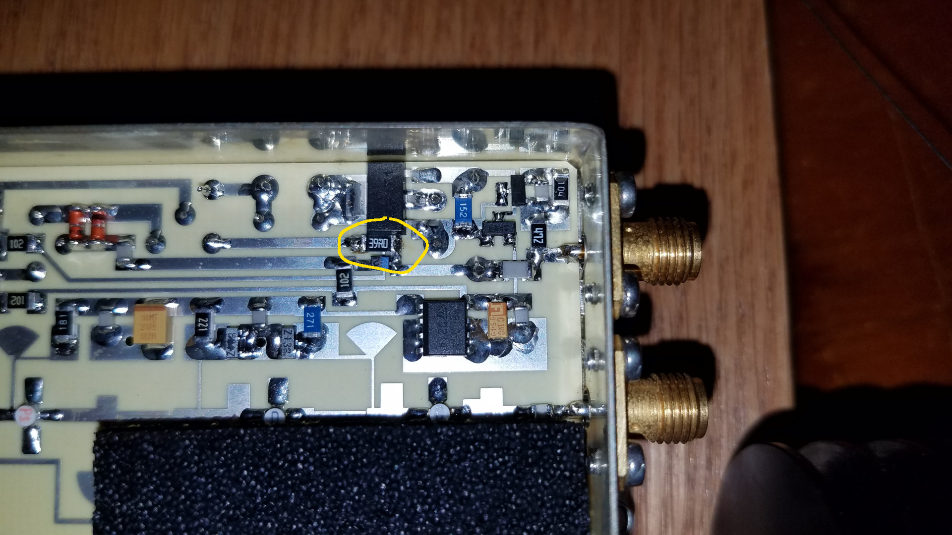
The Kuhne MKU 10 G2 transverter specifies 1 to 3 watts drive at 144 MHz for 200 milliwatts out at 10 GHz. When I tested the stock transverter driven by a G4DDK Anglian 144/28 transverter, my measurement setup showed full output of +23 dBm with the input attenuator set for maximum drive and +20 dBm from the Anglian. I was surprised to see it reach full output with 10 dB less than specified minimum drive. For my installation, I plan on putting the Anglian in the shack and MKU 10 G2 on the tower, with about 4 dB cable loss between them. I was going to need to be able to drive it with 4 dB less, or about +16 dBm. A 2016 blog post by G4DBN discussed replacing the 220 ohm resistor in the MKU 10 G2 input pad with 39 ohms when driven by the Anglian transverter, so I made that modification. After modifying, I measured exactly the same RF output at 10 GHz with 10 dB less drive at 144 MHz. I could get another 0.5 dB out of it by increasing drive 4 dB. Clearly it is being driven well past its linear region, but I found even at 5 to 6 dB less output it is not entirely linear. Since I don't expect to be doing much, if any SSB and have no close 10 GHz neighbors I am not concerned with this. The MKU 10 G2 says the DC voltage at its MONitor output should be greater than 1.2V at 200mW out. I am barely seeing 1.21V but I don't know what the impedance of the cheap DMM used to measure it is. I am interested in using an analog meter for monitoring that MON pin, so I tried putting a 10K ohm resistor from the MON pin to ground. That would be the approximate value if using a 100uA meter movement. This dropped the voltage at the MON pin to 0.93V so clearly it is very sensitive to load impedance. Perhaps with a higher quality DMM I would see more than 1.21V. I have two videos of testing on my Youtube channel: before modification and after modification. There are also videos on Checking my ability to measure power and Anglian transverter testing.
I checked the MKU 10 G2 / Anglian transverter combination on receive. All is well with some frequency drift as expected. I put a video of this testing on my Youtube channel: Receive tests.
Since it will be some time before I am able to put a full 10 GHz station on the tower, I am trying to put the
receive-only system used last year for EME experiments at 100+ feet on the southwest tower to see if I can hear
any terrestrial signals on 10 GHz. There is a challenge even in this. I have just one spare coax running to that
tower. It is approximately 370 feet of 3/4" CATV hardline. 250 feet of the cable run to that tower is direct
buried. It is neither a simple nor inexpensive matter to add another run of cable. If I were using an unmodified
LNB on the dish, this would be simple: a TV power inserter to put DC power on the coax and take the 618 MHz IF off
to the SDR. I wish to use the modified LNB which also needs a 25 MHz reference on a separate connector. I will try
to use a pair of SV1AFN DC-10MHz-VHF/UHF triplexers to run DC, 25 MHz, and 618 MHz over the single coax. It looks
like these have insufficient isolation of 25 MHz from the UHF ports so I will be adding high pass filters in the
UHF lines. Here are results of initial tests on two SV1AFN triplexers and a Holland RF power inserter:
Triplexer, 10 MHz into 10 MHz port:
Insertion loss (10 MHz at common port): .25 dB
Isolation, 10 MHz at UHF port: 46 dB
Isolation, 10 MHz at DC port: unit 1, 52 dB,
unit 2, 42 dB
Triplexer, 25 MHz into 10 MHz port:
Insertion loss, 25 MHz at common port): 1 dB
Isolation, 25 MHz at VHF/UHF port: 27 dB
Isolation, 25 MHz at DC port: unit 1, 22 dB,
unit 2, 21 dB
Triplexer VHF/UHF into VHF/UHF port:
Insertion loss (VHF/UHF at common port): 0 to 5 dB .1 to 1 GHz
Isolation, VHF/UHF at 10 MHz port: unit 1, 35 to 70 dB .1 to 1 GHz,
unit 2, 30 to 60 dB .1 to 1 GHz
Power Inserter, 25 MHz into RF port:
25 MHz at RF and DC port: 0 dB
Isolation, 25 MHz at DC port: 56 dB
Power Insterter, VHF/UHF into RF port:
VHF/UHF at RF and DC port: 0.5 to 2 dB
Isolation, VHF/UHF at DC port: -65 to -45 dB .1 to 1 GHz
This looks OK excpet for isolation of 25 MHz from the triplexer VHF/UHF port. With approximately +13 dBm
25 MHz reference, this would result in about -14 dBm at the SDR input and a couple dB less (feedline loss)
at the LNB IF and power port. That might work but I am not comfortable with it and plan to add 400 MHz high
pass filters to the UHF port at both triplexers. Although probably not necessary, as a learning experience
I may experiment with adding a second choke to the DC port in the triplexers to see if I can attenuate
25 MHz a bit more there. Of course I could modify the low pass and high pass filter sections of the
triplexers to get better rejection of 25 MHz on the VHF/UHF port but I prefer to leave them as they are
for possible future use with a 10 MHz reference. If you are bored and need to kill a half hour, see also my
video on these tests: Triplexer and power inserter tests.
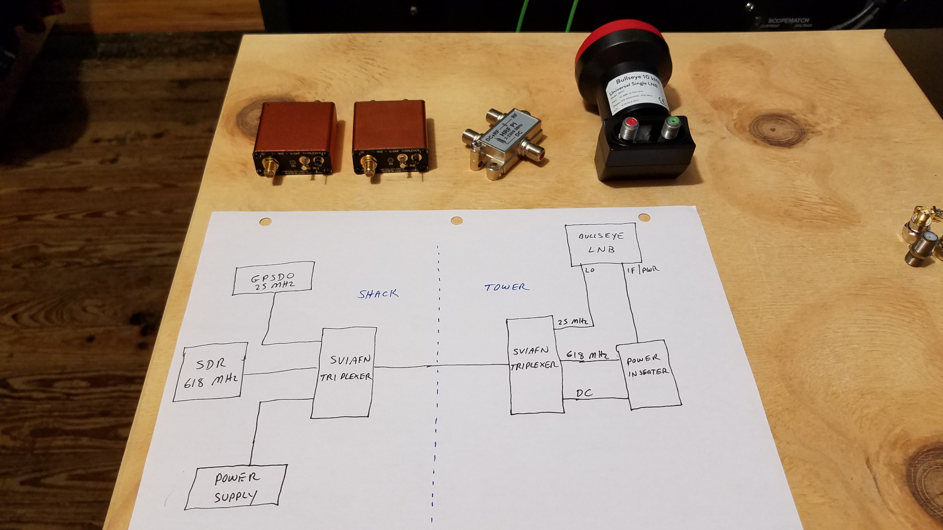
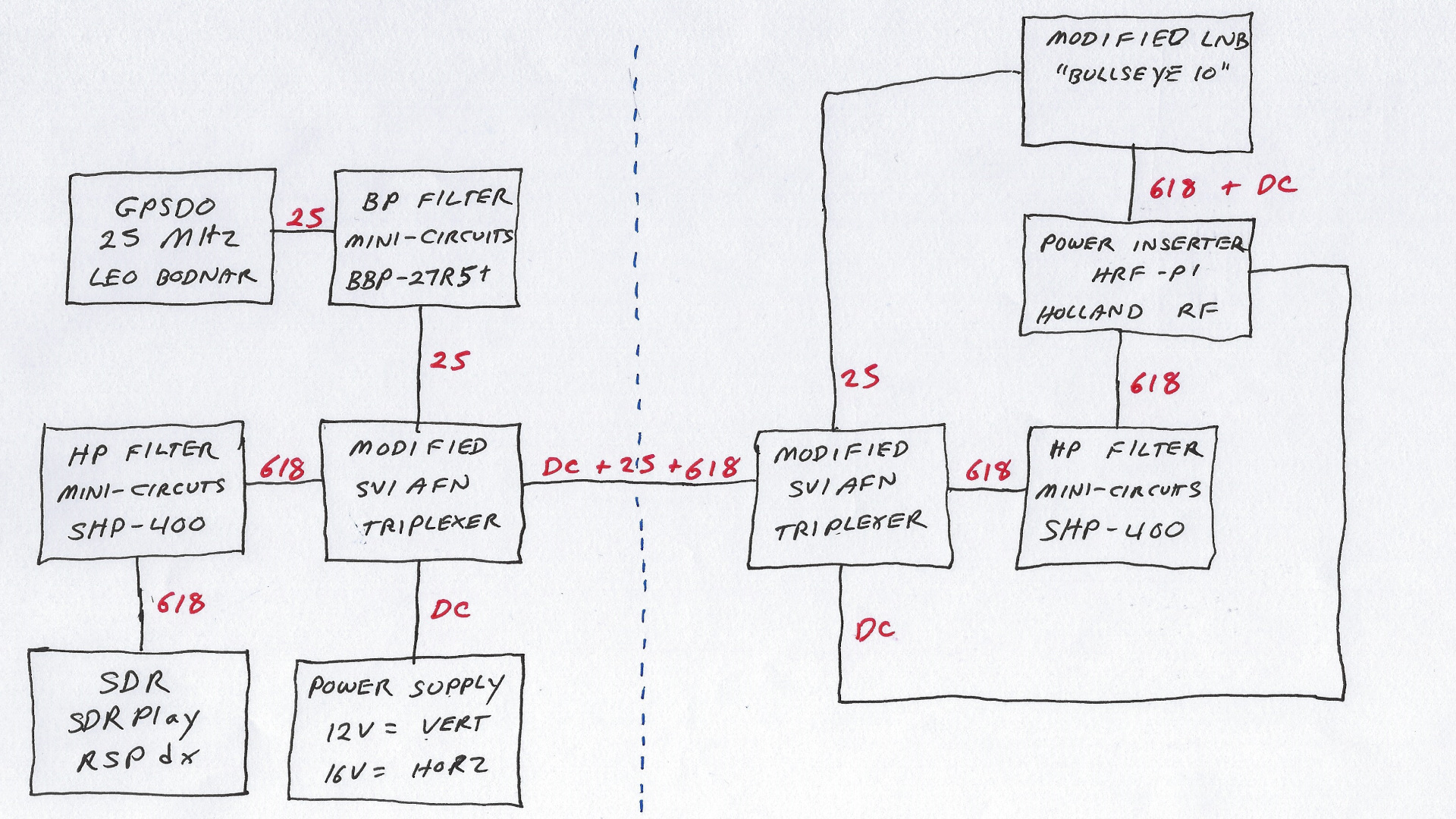
Any simple project can be made complicated! Using a LNB on a dish for 10 GHz receiving is simple. All you need is the LNB, a dish, a power inserter (bias tee), software defined receiver and a power supply. If you insist, as I do, on GPS locking the LNB LO, and moreover if you must or insist on using one coax to transfer DC power, LO reference and IF, be prepared for some complexities.
First off, you need a LNB that takes an external GPS derived reference. This is easy if you choose the Bullseye 10 kHz LNB, as I mentioned last year during my EME experiments. All you need to do is open up the LNB and remove the internal TCXO. The second connector can then be used to input a 25 MHz stable reference with no further modification required.
I found the LNB did not want to lock to a square wave reference, so I added a Mini-Circuits BBP-27R5+ band pass filter to filter out the harmonics and leave a nice clean sine wave.
Next there is that bit about combining DC, 25 MHz and 618 MHz on one coax. As discussed above, I found a pair of SV1AFN DC/10 MHz/VHF-UHF triplexers can be used. They are operating outside specifications with 25 MHz instead of 10 MHz and 618 MHz instead of 144 or 432 MHz RF. I ended up adding a 10 uH molded choke and a 0.1 uF capacitor to the DC port of each triplexer. That got the 25 MHz level at the DC port down to about -40 dB. It did reduce isolation in the upper VHF range at the DC port but that is of little concern for this project. 25 MHz level at the SDR was about -20 dBm and at the LNB IF port -25 dBm. I was not comfortable with those numbers so I added a pair of Mini-Circuits SHP-400 high pass filters.
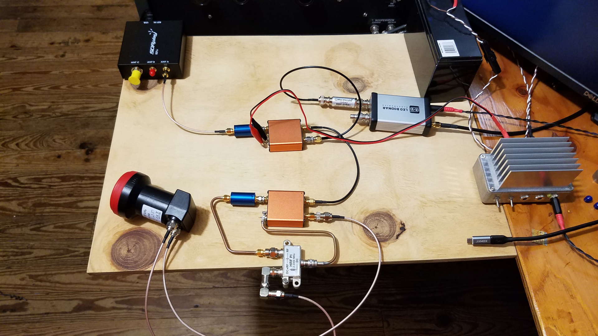
The final system shows end to end insertion loss of 3.6 dB at 25 MHz, 4.0 dB at 618 MHz. The latter is of no concern since the LNB sets the system noise figure and has more than enough gain to overcome losses in the triplexers and coax. I wasn't sure about the 25 MHz loss. I have +11 dBm at 25 MHz ouf of the band pass filter. I measured +5 dBm at the LNB LO reference port. I cannot explain why that is 6 dB down when loss measurement was 3.6 dB. I was concerned the level might be too low for the LNB LO synthesizer to lock to after including coax loss of about 2 dB but I added a 6 dB attenuator and it still locked up OK. It appears there won't be a problem there. The level of 25 MHz RF at the SDR input was measured at -120 dBm and at the LNB IF port -95 dBm. A test on the bench showed that everything is working. I made a video during the system bench test.
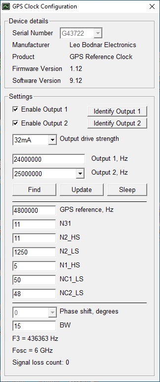
I received a very quick reply to my support request from Leo Bodnar Electronics regarding whether the dual output GPS reference clock (GPSDO) can provide both 24 and 25 MHz. It can. Therefore I can use it to provide 25 MHz reference to the LNB and 24 MHz reference to the RSPdx so the entire system will be GPS locked. The procedure is start the app, search for 600 MHz. Then multiply NC1_LS by 25 and NC2_LS by 24. There should be values of 2 in there after the search, so you enter 50 (2x25) for NC1_LS and 48 (2x24) for NC2_LS. Click update, wait a moment, then close and restart the app. It should now show 24 MHz for output 1 and 25 MHz for output 2. There are some close in spurs but they are more than 50 dB down so this should not be a concern.
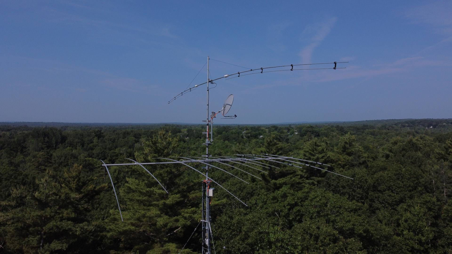
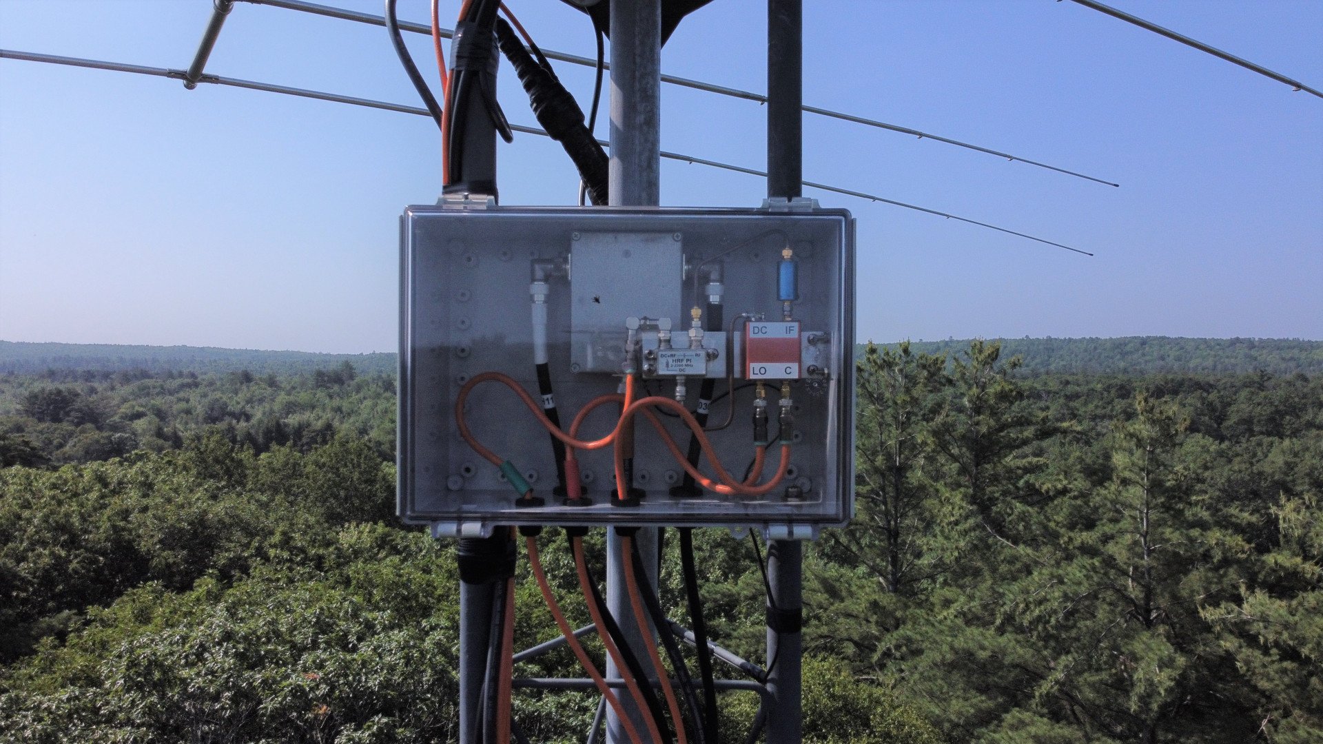
I am feeling a bit discouraged today, but I will regroup. Maybe I need some time away from 10 Ghz projects as there is so much that does not go well. Here are a couple images of the receive-only setup on the tower. The bad news is it doesn't work. It is comepletely dead with no signal from the LNB. The problem could be many things. I have tested as far as where the RG-6 from the shack connects to the 3/4" CATV harline under the house and all is well to that point. Testing on the tower will be very limited in the current hot weather. In the first image, the dish is pointing 320 degrees but the camera is looking approximately 250 degrees. The second image is the triplexer, filter, and power inserter in the box. The other item behind is a relay for switching a run of LDF5-50A between the TH-11DX and OB1-4030. Yep, that's a bug (not to be confused with a BUG) on the cover of the box.
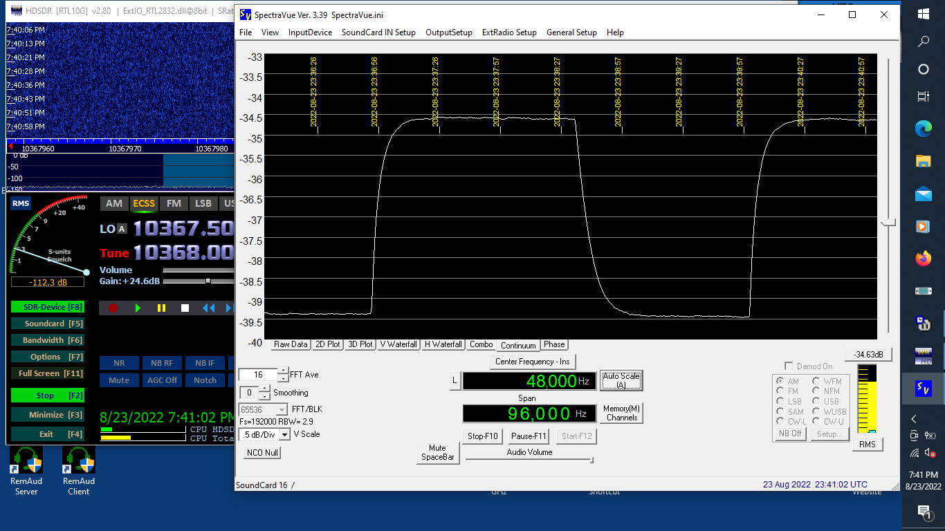
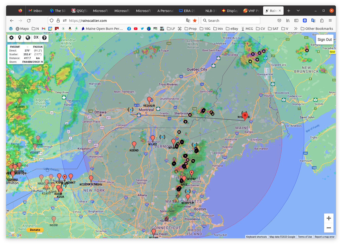
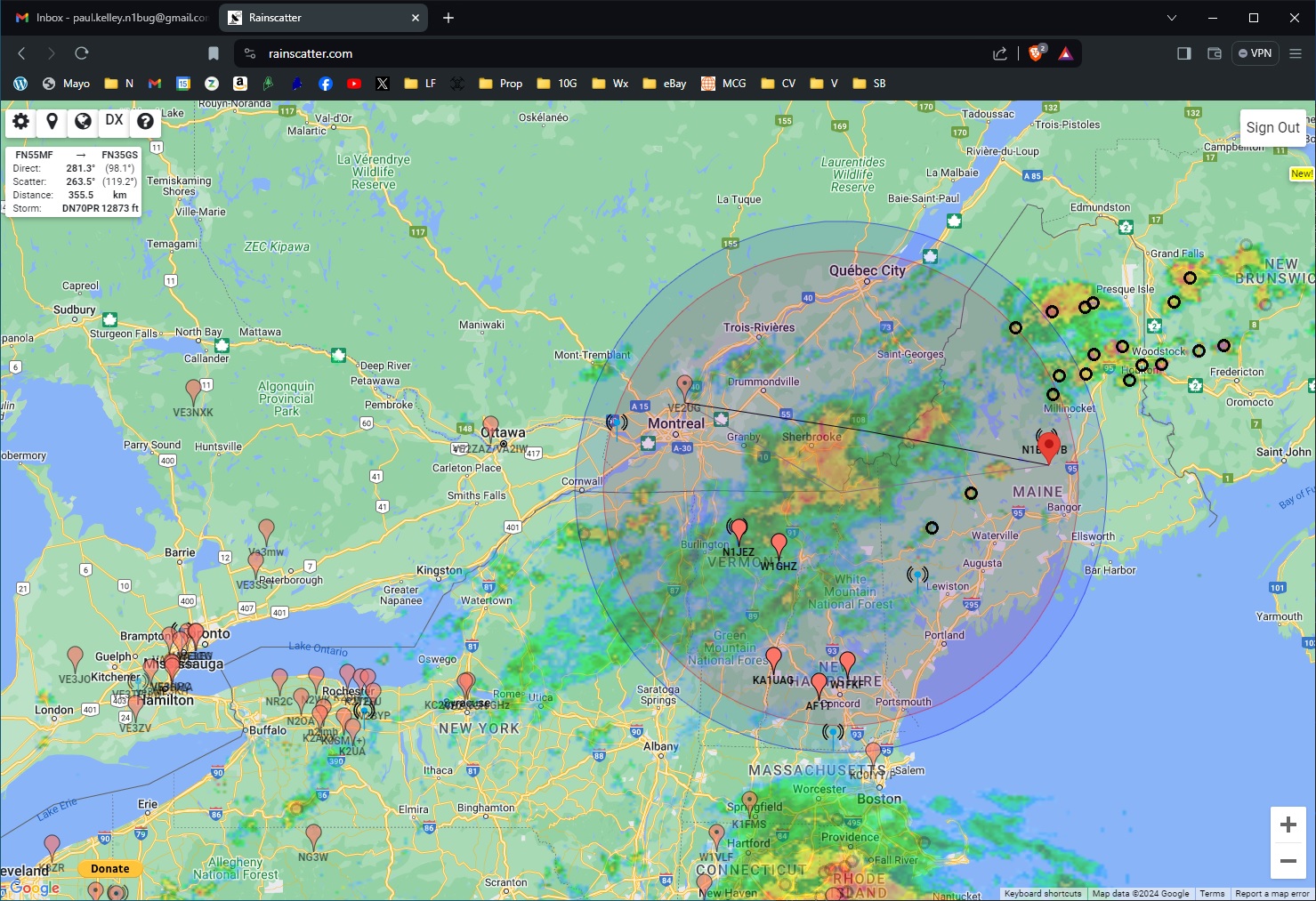
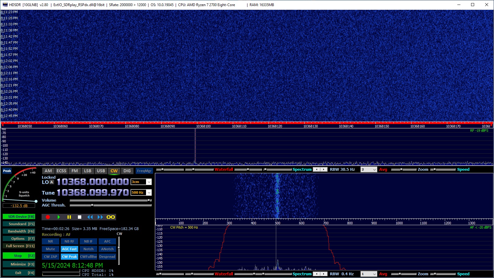
Problems continue but I heard my first 10 GHz terrestrial signals!!! I copied N1JEZ beacon and VE2TWO beacon on rain scatter. I did not manage to catch the very best of them in recordings or videos. I was going crazy trying to save files, record video and take screen captures all while fighting to track storms with a rotator that is having pulse counting issues, thus does not know where it pointing half the time. The first image below is a screen shot showing the two beacon signals in HDSDR. Shortly before I captured that screen shot, both beacons were peaking to -110 dB, a full 20 dB above the noise! The second is a screen shot of rainscatter.com a moment later, showing the storm that was providing propagation. The third shows the storm that caused less spreading of the VE2TWO beacon signal. Note how it is closer to being in a direct line between me and the beacon. There is also a video.
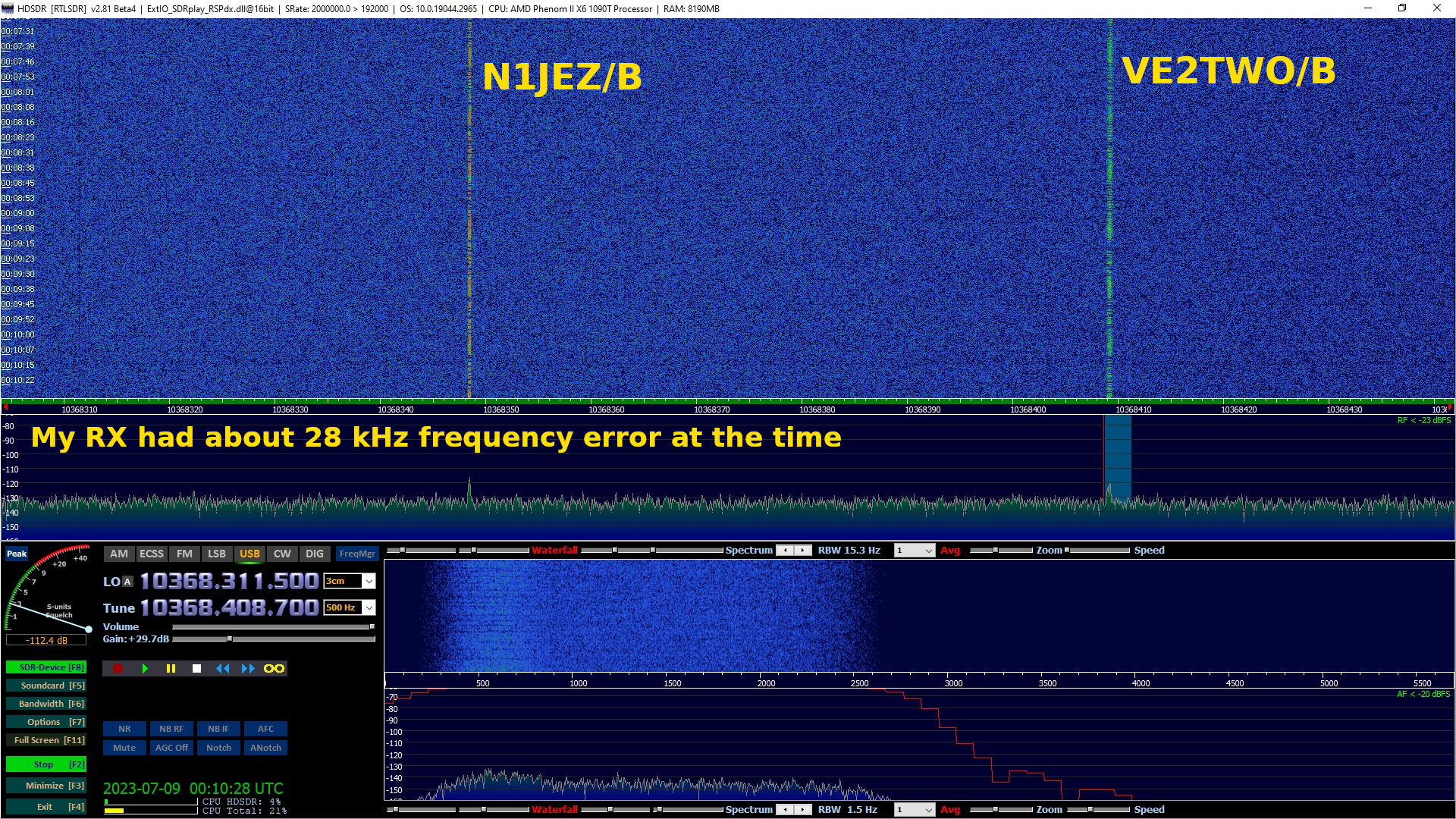
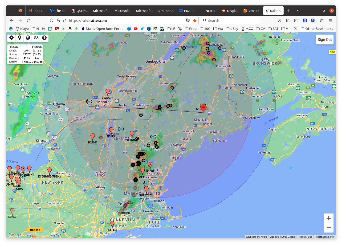
VE2TWO beacon weaker but with less spreading
On July 9, W1GHZ provided a signal for me to listen for via rain scatter. He was very readable with wide signal spreading. Paul says he was going through more than one storm cell. Fascinating! On July 10 I returned my temporary beacon to the hill 5.6 miles away for testing. The beacon runs about 5 milliwatts to a small indoor antenna and there are two lines of trees in the path. The beacon uses the 10 MHz OCXO in the microwave weak signal source, the VHF Design PLL bpard in the power and return loss meter, and a small WA5VJB LPDA antenna inside the building. It has to bet through two thick lines of trees in the path to my home station. There is also a video with much the same information presented here.
Audio clip of W1GHZ on rain scatter
Audio clip of temporary N1BUG beacon
Some reflections (no pun intended) on the journey to this point...
It has taken two years since I started down the 10 GHz path to get a receive system on the tower. I have had a lot of fun along the way and I have learned a lot, which is what I was looking for. This learning curve has at times been more frustrating than most in that I have failed to avoid purchasing mistakes that set back progress. As a result it is going to take longer than expected to get a full station up and running, and also longer than expected on the permanent beacon. Beacon design work is just not going well but I am determined and will succeed in the end. The biggest challenge for my home station remains getting sufficient DC power, PTT and any other control or telemetry signals from the shack to the dish location which requires over 350 feet of cable. There are a few possible ways to do it, each with pros and cons. Any of them will be quite expensive, probably a year's savings or more. In addition, my rotator is having intermittent pulse counting problems, causing it to get out of sync with the controller so I don't know where it is pointing. I cannot be certain but I believe this is a control cable problem. At times when it is acting up I measure as little as 3000 ohms resistance between conductors in the cable, when specs say it should be greater than 20 megohms. The cable was installed in 2006 and almost immediately had a water intrusion issue that resulted in water running out the shack end of the cable. What I am seeing now is probably a delayed result of that plus another water intrusion issue last winter, that one related to a poorly implemented junction box that came with a rotator. It was never a problem with the Ham IV or T2X rotators previously on the tower but the new Orion and Green Heron RT-21 uses a pulse counting system and seems unable to deal with it sometimes. When it is working correctly this new system can aim to within half a degree which is great for a 10 GHz dish having a 3 dB beamwidth between 2 and 3 degrees.
I needed to know for certain that terrestrial signals could be heard in this location before putting so much of my limited resources in to the build out. Thanks to W1GHZ and the beacon providers, the past few days have given me a huge morale boost. I now know with all certainty that I can work a number of stations on rain scatter. I will be proceeding with the station build but cannot offer any time line. Many things can happen which would have an impact on it.
Signals propagated over short paths are affected by environmental and weather conditions.
Audio clip of N1BUG/b with a rain shower passing through
Audio clip of N1BUG/b with relatively dry, calm conditions
Audio clip of N1BUG/b direct and strong rain scatter at the same time
Also see the video for more on this event
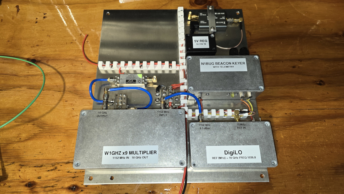
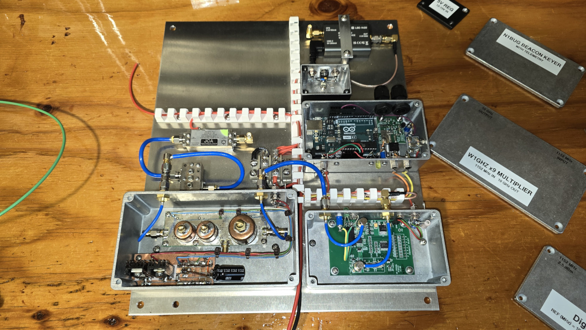
I am at something of a crossroads with the beacon project. I am at a point where it would make sense to start mounting things in the box, except that I don't know what the future power upgrade path is... or even if I should abandon all that I have done and go a different route entirely.
The current arrangement is a Q5 Signal DigiLO at 1152 MHz driving a W1GHZ x9 multiplier. This can produce a signal free of objectionable close-in spurs with the advantage that I can get some control over keying hardness (clicks) by adding a RC network to the keyed stages. However to control the spurs, the 10 MHz reference needs to be changed, for example to 10.000299 for a beacon frequency of 10,368.310, which is easily done if using the Leo Bodnar GPSDO. The DigiLO is programmed to generate 1152.000000. The actual output is 1152.034444 due to the reference being high in frequency. With a 10.000000 MHz reference, the output is not as clean when programmed for any frequency in the 10,368.3 to 10,368.4 range that the digiLO is capable of. The disadvantage is that after necessary filtering I have +7 dBm output. This is not sufficient to drive a DEMI amplifier to full output as I had hoped. So how do I ensure I can upgrade to the 1 to 5 watt power range later?
One possibility is to drive a DEMI amp directly with the +7 dBm. My guess is that might get me around 1.5 watts out, which is within the target range.
Another possibility is to use the Kuhne L101H amplifier I have to boost the +7 dBm to +17 dBm. This could then be attenuated down to fully drive the DEMI amplifier or used to drive a PE1RKI 50 mW in, 4-5 watt out amp, assuming that amp can handle beacon duty. I have not asked about that yet. The disadvantage of this is thermal inefficiency. The 101H is a 2 watt rated amp with 200 mW drive. It dissipates over 8 watts of heat idling or when producing 50 mW out. Heat is a concern in any beacon and that extra few watts could be important.
I am currently not aware of any efficient way to get from +7 dBm to anywhere in the +10 to +23 dBm range to fully drive any readily availalbe amplifier (DEMI +10 dBm, PE1RKI +17 dBm, Kuhne amplifiers +23 dBm).
The other possibility is to scrap all of what I have and save up for a Kuhne MKU LO 8-13 PLL-2. It can act as a beacon with internal or external keying. According to the detailed specifications, it typically produces around +15 to +16 dBm output at 10,368. After necessary filtering that would leave enough to fully drive a DEMI amplifier. However that unit is extremely expensive for my budget and there are unanswered quetions such as how hard (clicky) is the keying using internal or external CW genearation and what about close-in spurs when generating a desirable beacon frequency such as 10,368.310. I have seen first hand many synthesizers that look great at 10,224 or 10,368 are anything but clean when forced into fractional N mode to generate one of these more challenging frequencies. It may be possible to bump the 10 MHz reference as I have done with the digiLO but this too is an unanswered question. External keying would be preferable since when using the Arduino keyer I can add dynamic information to the beacon message, such as beacon internal temperature. I consider this a desirable function since I don't know enough to predict what the internal temperature might get to on hot summer days and may need to develop measures to keep it under control.
Since getting the receive system up here at home, I have discovered how helpful a beacon is to me. My Orion rotator can aim to within 0.5 degree but sometimes has pulse counting issues which cause it to get out of calibration. Having a local beacon that I can use as a heading check makes getting it back on track so much easier. The beacon is also useful as a frequency marker, not just to me but to anyone else in the area trying to receive on 10 GHz. Not to mention that just having a reliable local signal is very helpful. The temporary beacon setup I have on the hill now works for me but probably isn't receivable by others. I also need the pieces is it built from back here at the test bench! I need to at least get a permanent low power beacon installed as soon as possible. As far as a future high power upgrade goes, I am being stubborn about that. Whatever aspect of amateur radio I am into, I am always looking for the formula that provides the greatest personal benefit and satisfaction. The beacon project is a factor in that.
Regarding what I said about modifying the "Bullseye" LNB last year... forget it!
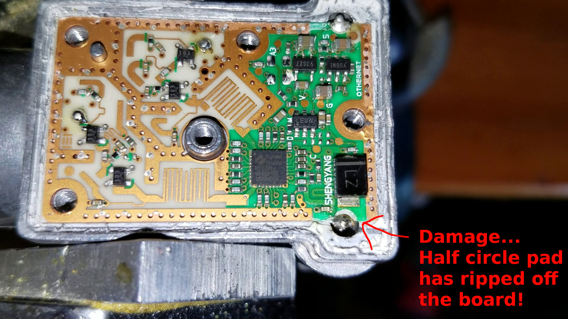
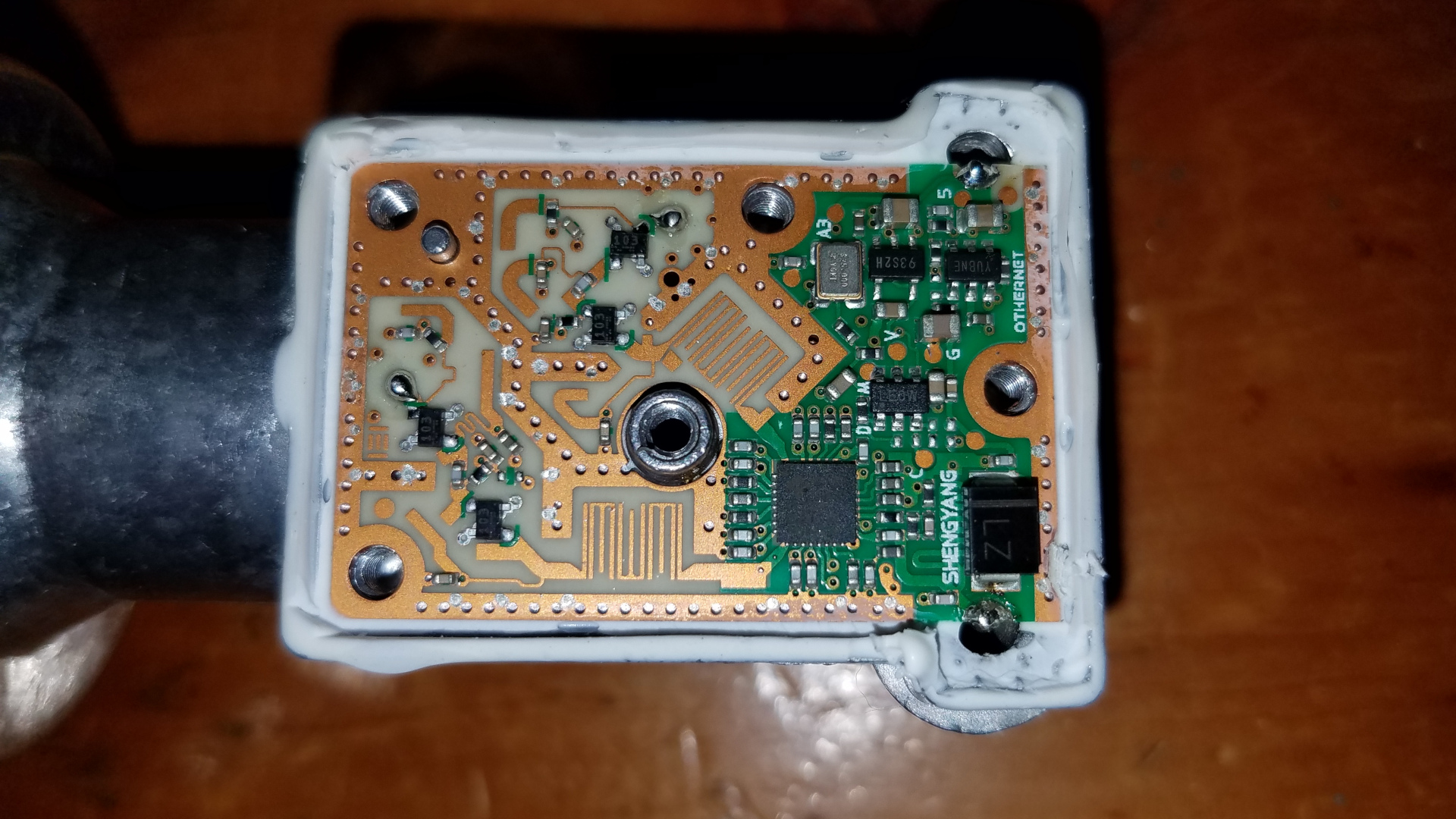
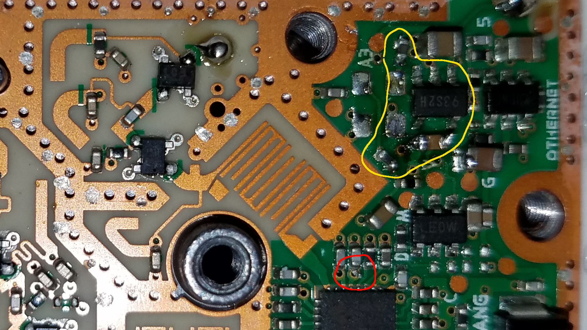
I reported on July 8 that after putting the modified LNB on the tower, it didn't work. I later discovered the reason: PCB damage that occurred when I modified it. I could not get the TCXO removed with the PCB in the metal case, because all the heat was going through the PCB and into all that metal which was acting as a heat sink. To solve that I removed the PCB. To do that, one must desolder the center pins of the two F connectors from half circle pads at the edges of the PCB. When putting them back it is critical that the PCB be pressed very firmly down against the metal housing, so that when the metal cover is put back on, it does not cause those pads to break away from the PCB. The cover presses down against the PCB. Here is an image showing the damage which did not manifest immediately but instead lurked and then popped up as soon as I put the thing 105 feet in the air!
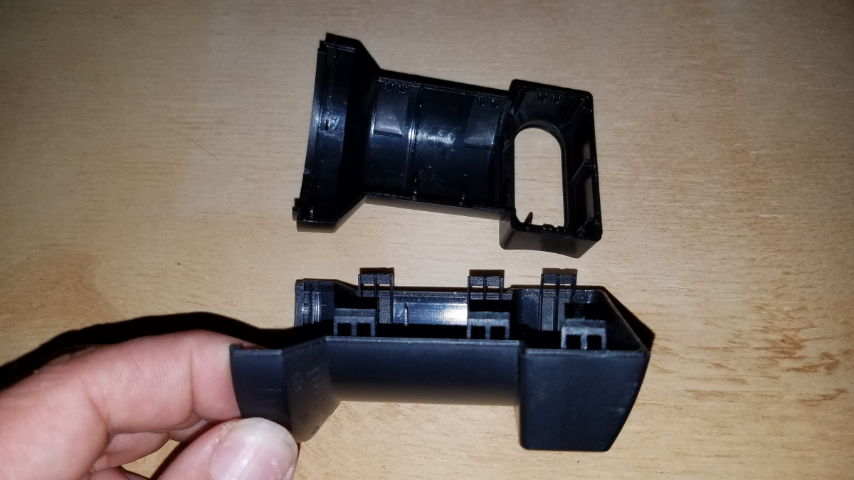
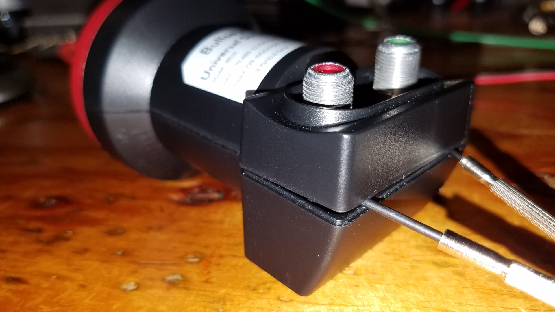
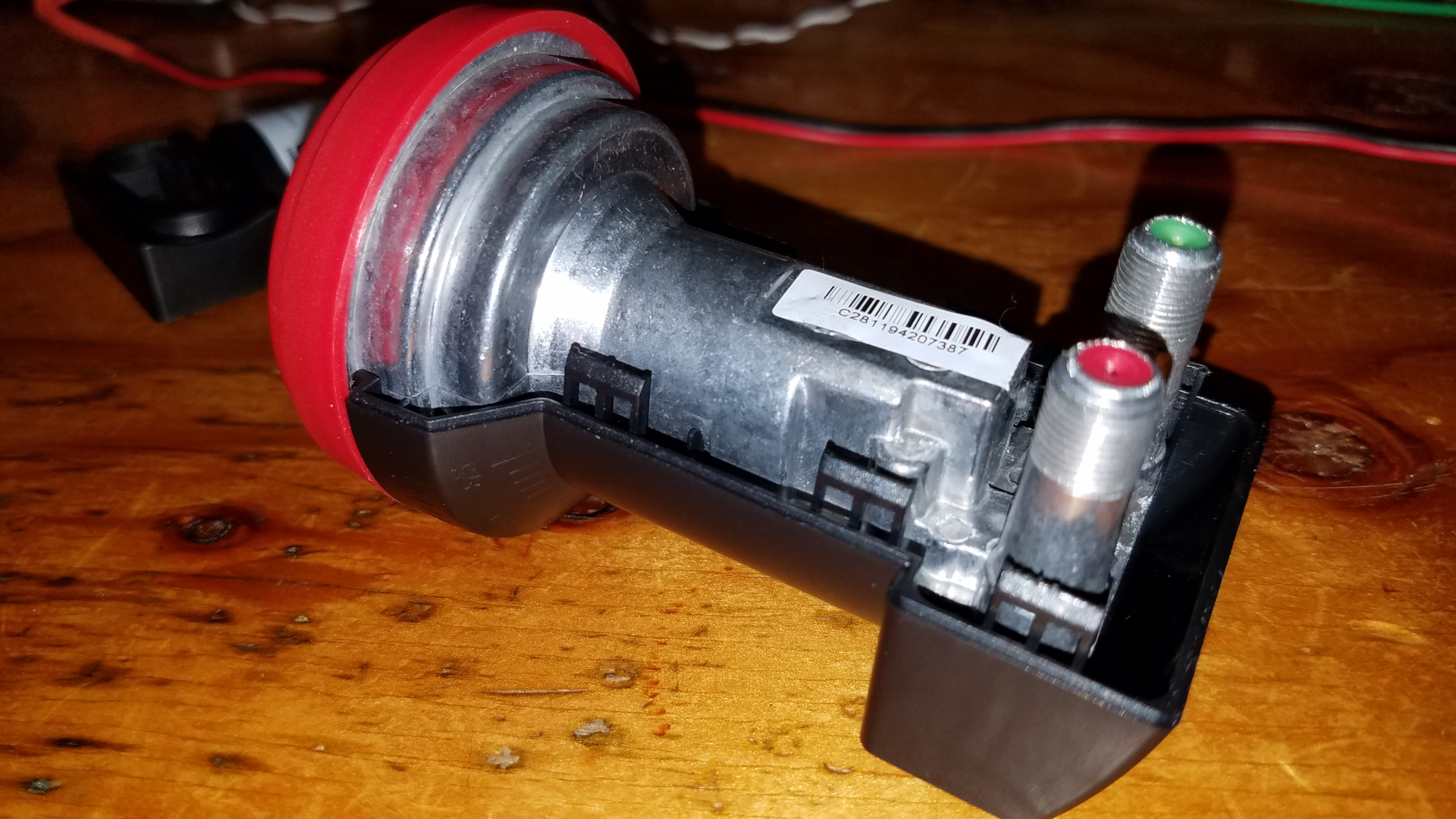
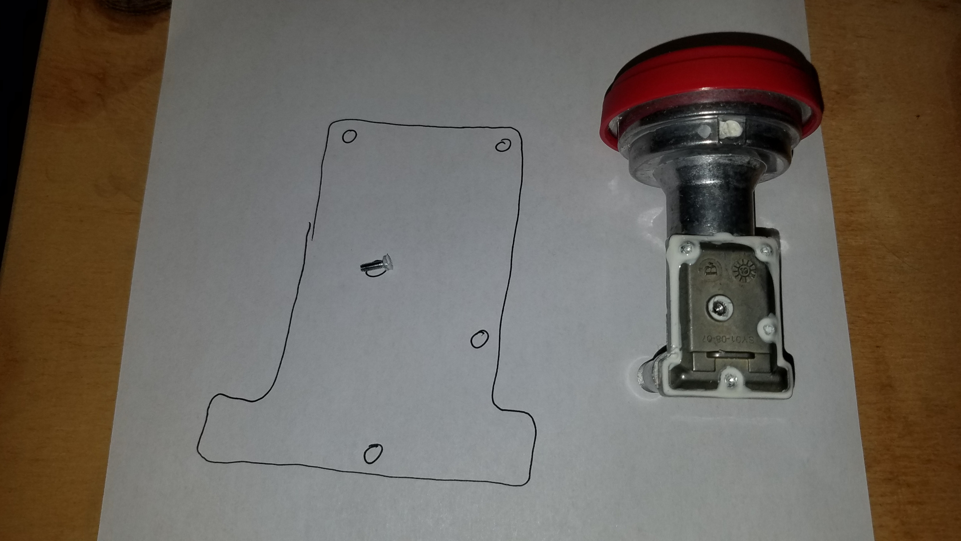
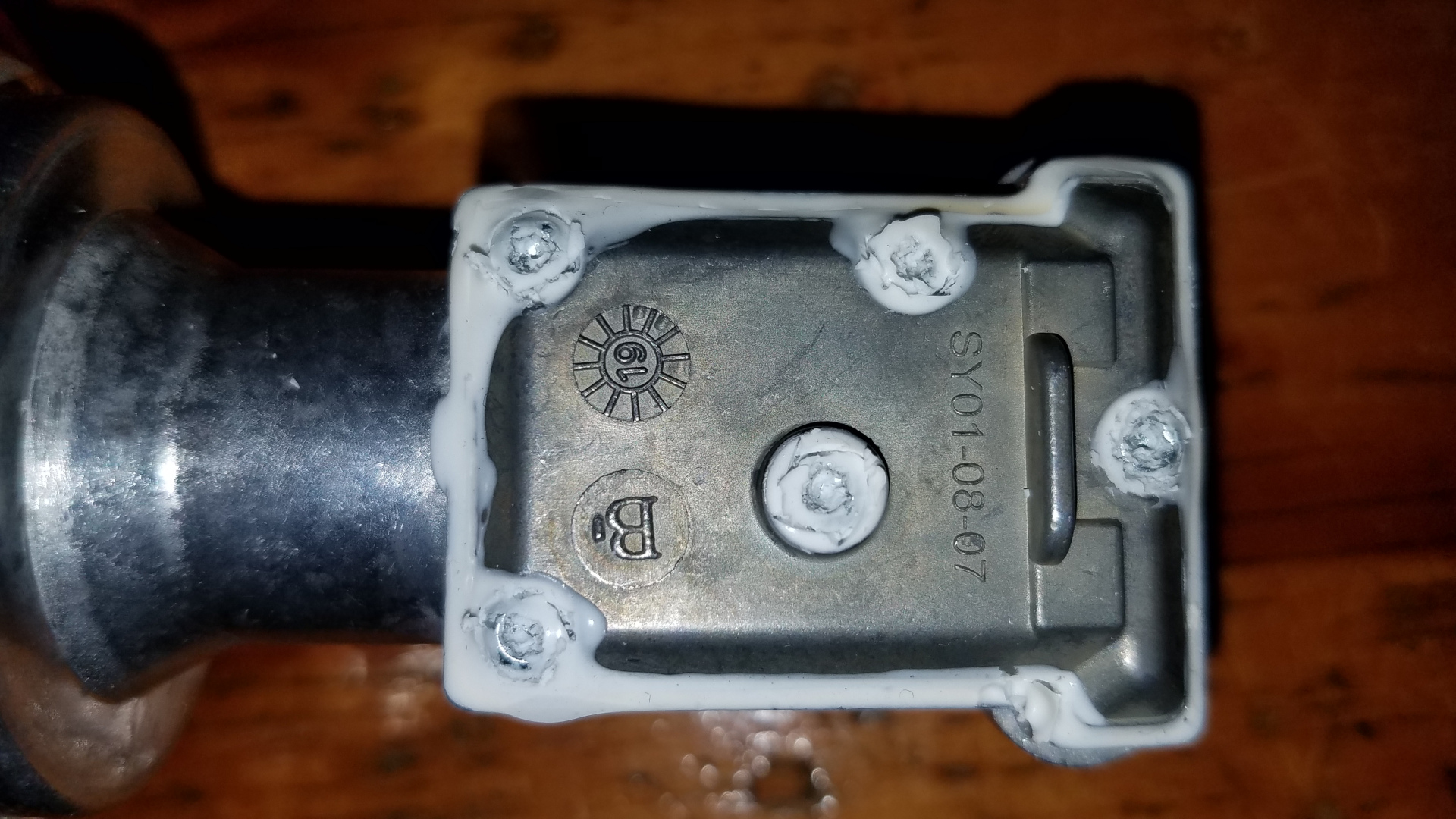
Today I tried the modification on a new LNB. I failed again. I did not want to remove the PCB this time. I set the hot air gun temperature to maximum, 500 degrees C, and started with modest air flow. The metal case got plenty hot but the TCXO would not let go. I incrementally increased air flow but long before the stubborn TCXO let go of the board, other SMD components were sliding around and blowing away in the hot air stream. Some of these are scarcely bigger than a speck of dust and I am unable to place them back where they belong, even if I could have kept track of what went where. I did not take a photo of the carnage, as I was too frustrated. On a positive note, I have become quite good at getting the plastic case apart without breaking any tabs and the sealed metal lid inside off. Here are a few photos, but they don't tell the whole story. I start by reaching down beside one of the F connectors with a very small screwdriver to pry one locking tab open, while using a thumbnail to try to wedge the case apart a bit in that corner. When it begins to open, I put the tip of a small screwdriver in there to keep it from snapping back together. I then go to the other side and do the same thing to the tab there, and put another small screwdriver between the case halves to keep it from snapping shut. A firm squeeze of the case top (bottom in the photo as the LNB is upside down) will pop the remaining four tabs open and allow the two halves of the case to be pulled apart and out from under the lip on the red plastic cap.
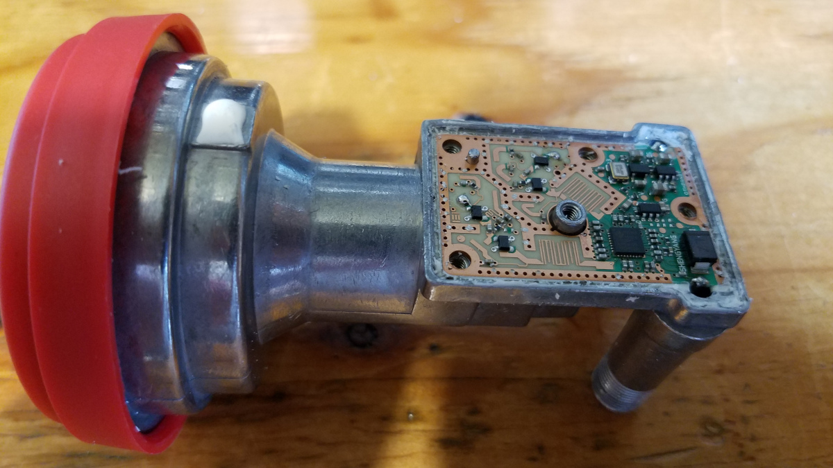
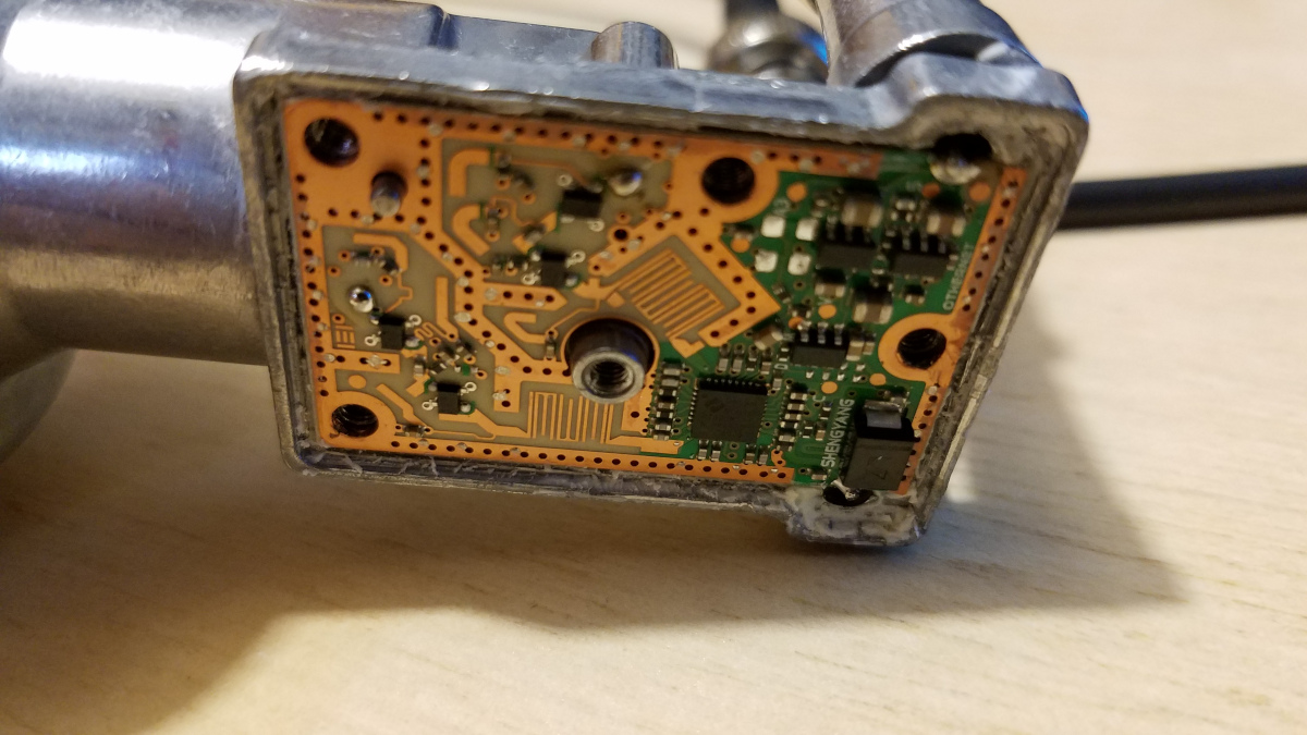
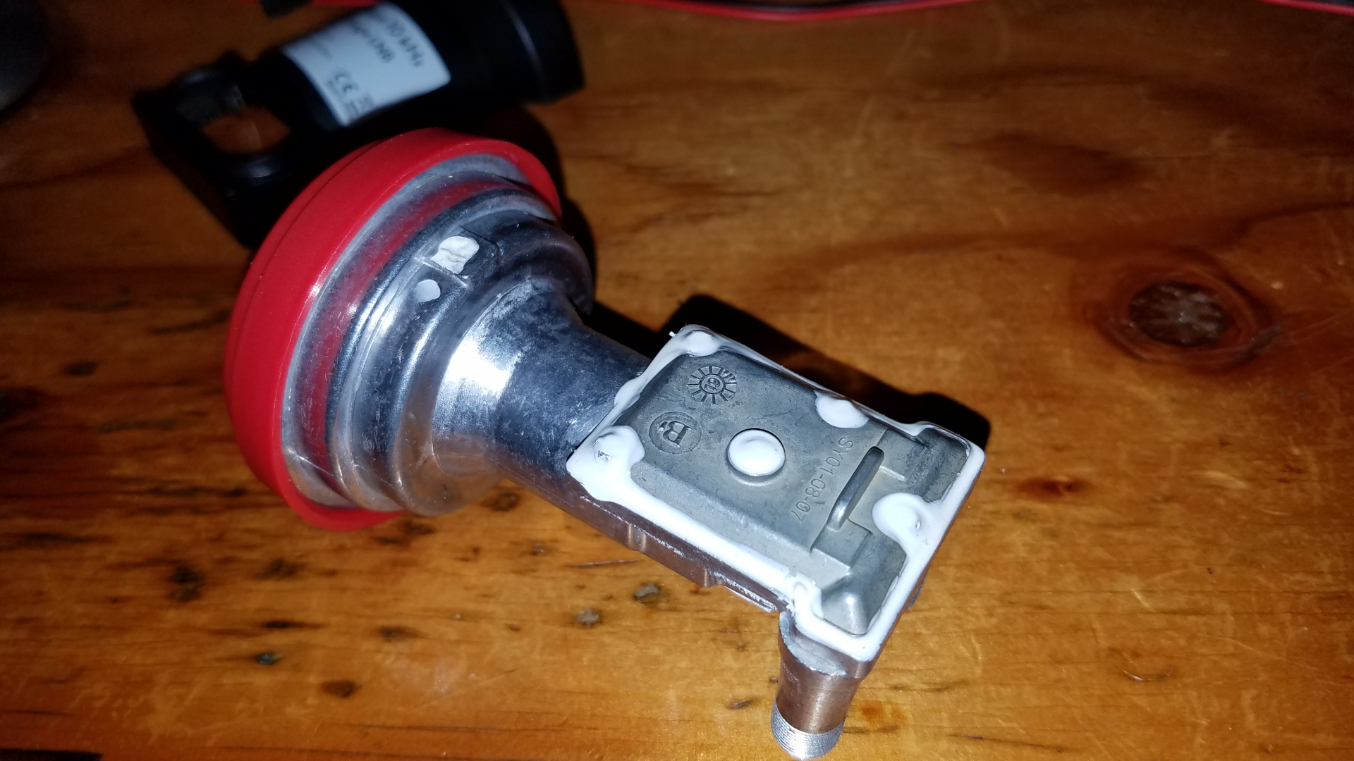
Next I clean some of the white sealant out of the screw torx heads with a tiny flat blade screwdriver, then with an X-acto knife I cut the sealant around the screw head, leaving as much of it intact as possible. I then cut all the way around the perimeter of the lid. Finally I use a tiny screwdriver to pry under the edge of the lid. It comes off pretty easily. I like to keep track of which screw was where and put them back in the same spots, though I do not think it matters. The last photo is the internals of the LNB before I destroyed it.
This really bugs me. Removal of just that one part, the TCXO, is all that is required to have a LNB that can use a GPSDO reference. The problem is how to remove that part without damaging anything else. I was curious whether it might be possible to get the TCXO hot enough by applying a large soldering iron tip to the top of the TCXO, but I think not. I placed the removed TCXO on a small piece of aluminum and heated it for quite a while with a large, HOT soldering iron but the piece of aluminum I had it sitting on barely warmed up at all. I cannot think of any other technique to try. I hate to give up but I am out of ideas and I cannot afford to keep buying these things only to destroy them.
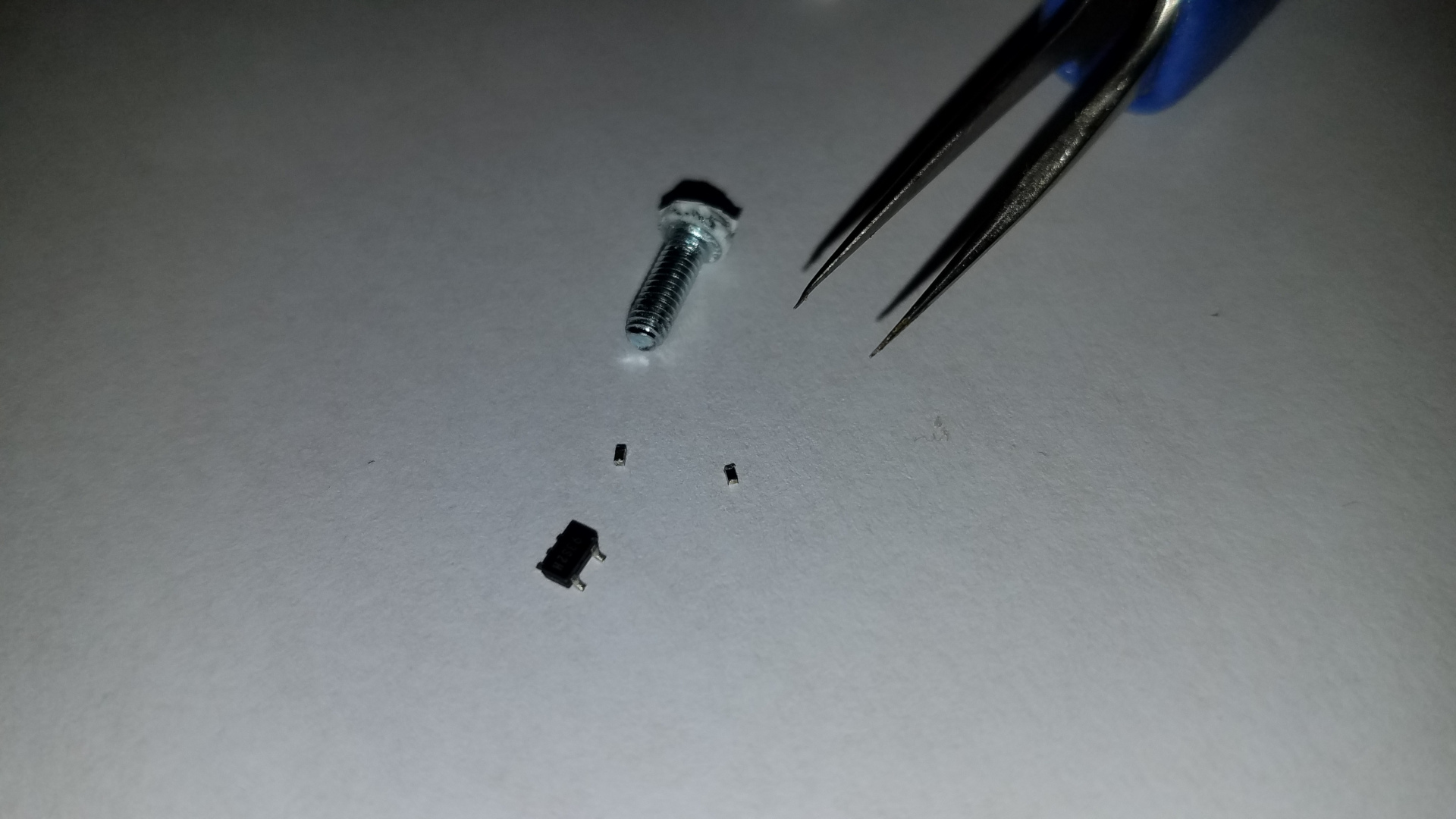
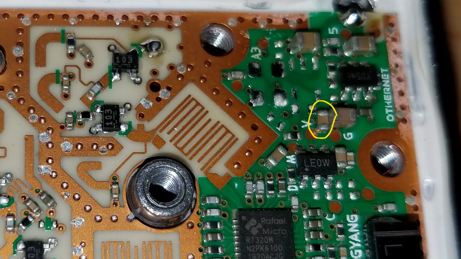
I was up at 2:00 AM thinking about yesterday's LNB fiasco. I found some of the small parts (first photo) easily enough. They had moved to new locations on the PCB but had not fallen off onto the bench or floor. I had seen them move so I knew where they were. One I did not see move, and at the time I didn't know where it had ended up. I knew it was missing but didn't see it anywhere. This morning I found it (second photo). It had reoriented and moved only a little, soldering itself to another part! I should have noticed it there more easily. I was able to retrieve it with a soldering iron. Since I now had all the parts I decided to have a try at putting them back in their original positions. I had litle confidence in my ability to do that but nothing to lose by trying. Getting them positioned just right and soldered down was tricky but after a few attempts I got it done! They don't look perfect (third photo). There is some excess solder on some of the parts but it doesn't appear to be doing any harm so I left well enough alone. Any attempt at removing it might cause the solder on both ends of a part to flow and the thing to move again. This is the 25 MHz and 3.3V regulator area, so presumably not super critical stuff. There was one other problem found - a small, loose solder remnant near another component. I only found it by taking a high resolution (4032x2268 pixel) photo for inspection purposes and scrolling around it full size on a 27 inch HD monitor. I was able to remove it with tweezers and took a new insepction photo (not shown). These photos make the parts look far bigger than they actually are! I was worried that parts on the other side of the board might have fallen off. But would they? They would not be blown around by the hot air on the back side of the board, and even though gravity would try to make them fall off if the solder melted, I suspect the weight of the parts might not overcome the tendency of molten solder to hold them in place. I made no attempt to remove the board and check since that would invite a repeat of the problem I had with the first modified LNB. The fourth photo is with the internal cover reinstalled. Most of the sealant has been saved. Doees this do any good? I have no idea. It's how I chose to do this one.
OK, but would it work? It had taken a lot of heat yesterday to get that TCXO off. Could components have survived? And what about my repair attempt? I took it over to the shack and connected it up to the power supply, receiver and 25 MHz reference. It came to life and was drawing the correct amount of current, about 75 mA! I switched on a VHF Design PLL board as a way-too-strong signal source over at the bench and the LNB was hearing the signal! I can't be certain its noise figure is what it should be, but the LNAs are on the far end of the board from where this work took place and I think there's a very good chance they were not affected. I wanted to make sure the thing would be able to lock with the expected level of 25 MHz reference up on the tower, after passing through two rather lossy triplexers and over 350 feet of coax. First I put a 6 dB attenuator in the 25 MHz path, which leaves a bit more signal than what it will get on the tower. It locked right up. The only other attenuator I had conveniently available without resorting to a stack of between series adapters was 20 dB. Could it possibly be OK with a level that low? I tried and it locked right up! That was amazing, considering there is an attenuator in the LNB between that red connector that now serves as the reference input and the rest of the circuit. With the 20 dB attenuator, the level I am injecting to the red F connector on the LNB is on the order of -10 dBm! Yet is seems to be enough. This is about 10 dB lower level than what it should get on the tower, so things look promising. When weather permits I am going to go ahead and install this up at the dish and see what happens.
I made a very early morning climb to install the modified and repaired LNB. After connecting cables for the 25 MHz reference back in the shack, I held my breath as I hit the LNB power switch, more than half expecting no sign of life. But, it worked! I then broght the Leo Bodnar GPSDO back to the bench to reprogram it for 25 MHz on one output for the LNB and 24 MHz on the other for the RSPdx. Unfortunately that did not work. The LNB has problems with the reference when it it set up that way. A clean signal becomes several traces speced only a few Hertz apart and has a distinct warbling sound. I went back and forth a few times between the Leo Bodnar programmed for 25 MHz only and for 24/25 MHz and the result is repeatable. The 25 MHz looks OK on my spectrum analyzer. There are some spurs that are about 55 dB or more down. Whether those are enough to mess up the LNB I don't know. I suspct there is something else going on that I am unable to see on the spectrum analyzer. A vidoe is worth several thousand words, so I made one that probably contains several thousand words of my rambling on! Here it is. My solution to the GPSDO problem is to use both of my Leo Bodnar units, one for the LNB and one for the RSPdx. This works perfectly but leaves me with none to use at the bench when I am working on the beacon. I listened to my temporary beacon on the hill for about 8 hours and it never moved at all. What a nice improvement! The beacon does seem to be 40 Hz low in frequency but I suspect the beacon OCXO has drifted. It would take just .04 Hz at 10 MHz to equal 40 Hz at 10 GHz. When I tested and adjusted that OCXO on the bench July 8-9, it moved about that much in 24 hours, by which time it seemed to have settled down. But I woudn't be surprised that is has moved .04 Hz in the last 13 days on the hill.
A better solution would be some way to generate 25 MHz (and 24 MHz) with a 10 MHz reference. I could use my master bench and shack 10 MHz reference from the Trimble Thunderbolt. Unfortunately I have researched this a few times and do not know of a way to do this. Most of the popular low cost synthesizers start at around 35 MHz.
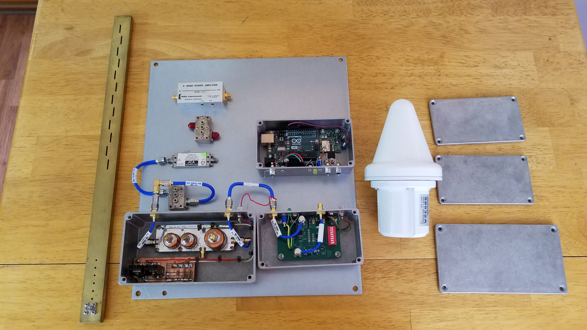
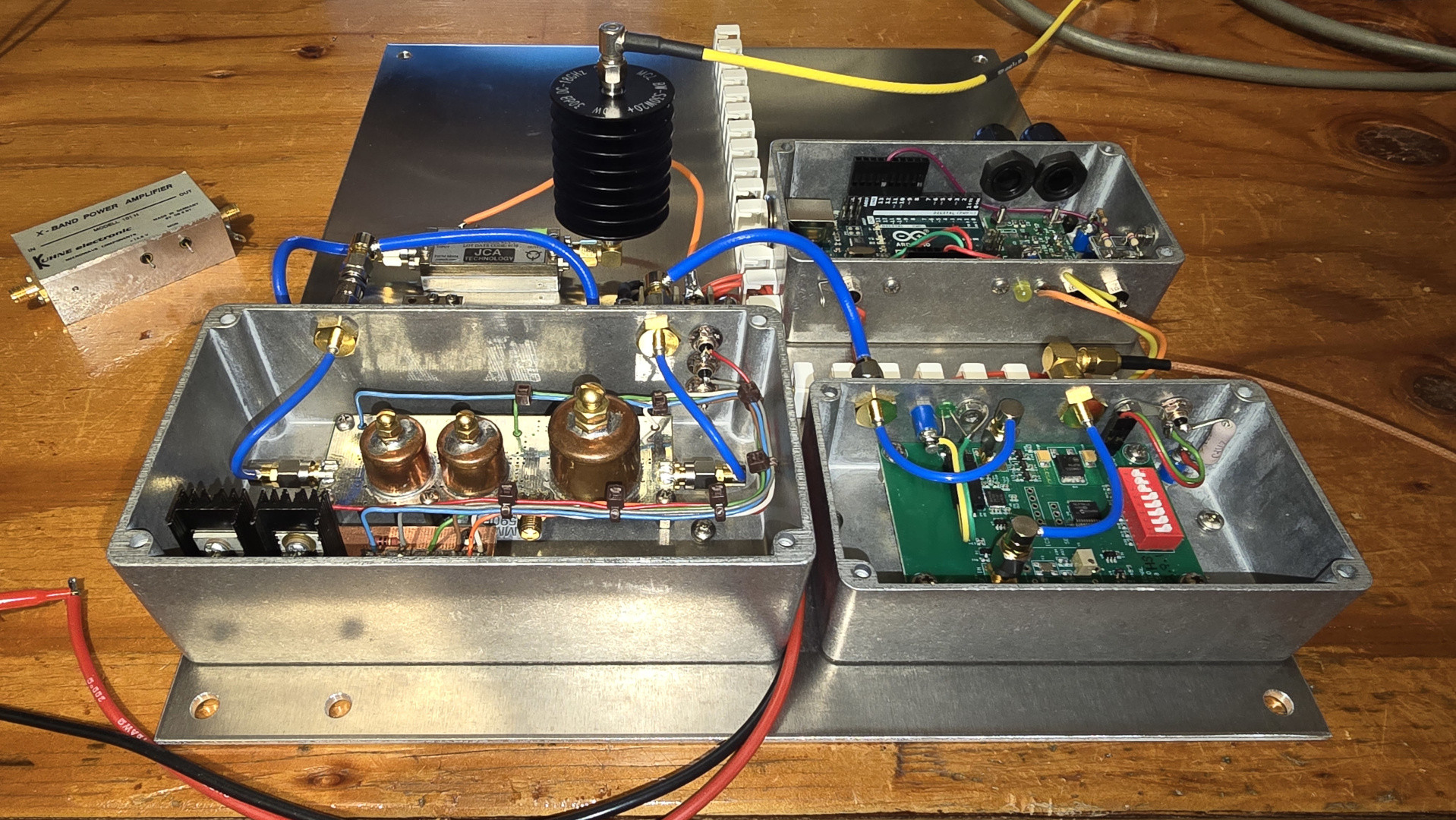
Last night, members present at the Piscataquis Amateur Radio Club meeting voted to approve my request to install a "high power" (1 to 5 watt) 10 GHz beacon at the site. I had originally sought approval for a 10 milliwatt beacon. I am very grateful for the support of this project. The photo shows current beacon design progress. I am awaiting more materials which should arrive in about a week. With my home 10 GHz receiving setup now complete and operational, the beacon is moving to the top of the project priority list. The amplifier shown should produce about 2 watts but I am unsure of its survivability in a beacon. This may or may not be the amplifier used.
Having received several very thoughtful questions after my brief talk about beacons at the PARC meeting, I wrote two articles aimed at those who know little or nothing about micrwaves.
Why Microwave BeaconsAfter the beacon is up and running I hope to make one or possibly two such receiving systems (minus the computer) available for loan in the local area.
Over the past few days I got several beacon sub-assemblies mounted on the plate and did some wiring. In testing today, power output from the multiplier was 19 dB below what it had been last time I checked it. The problem turned out to be two bad SMA right angle adapters. One of them was in the 1152 MHz path and didn't even work at that frequency, where it had more than 15 dB loss. I can't say I am surprised. I have barely had any connectors, adapters, attenuators or cables that I bought as used or new old stock that were any good. So far I haven't had a problem with any cable, adapter or attenuator bought from Mini-Circuits. The solution here will be to buy two Mini-Circuits cables with a right angle connector on one end. Another delay and another expense. I will not buy any more of such items that are not new and from major reputable vendors. No more eBay or surplus purchases on these items!
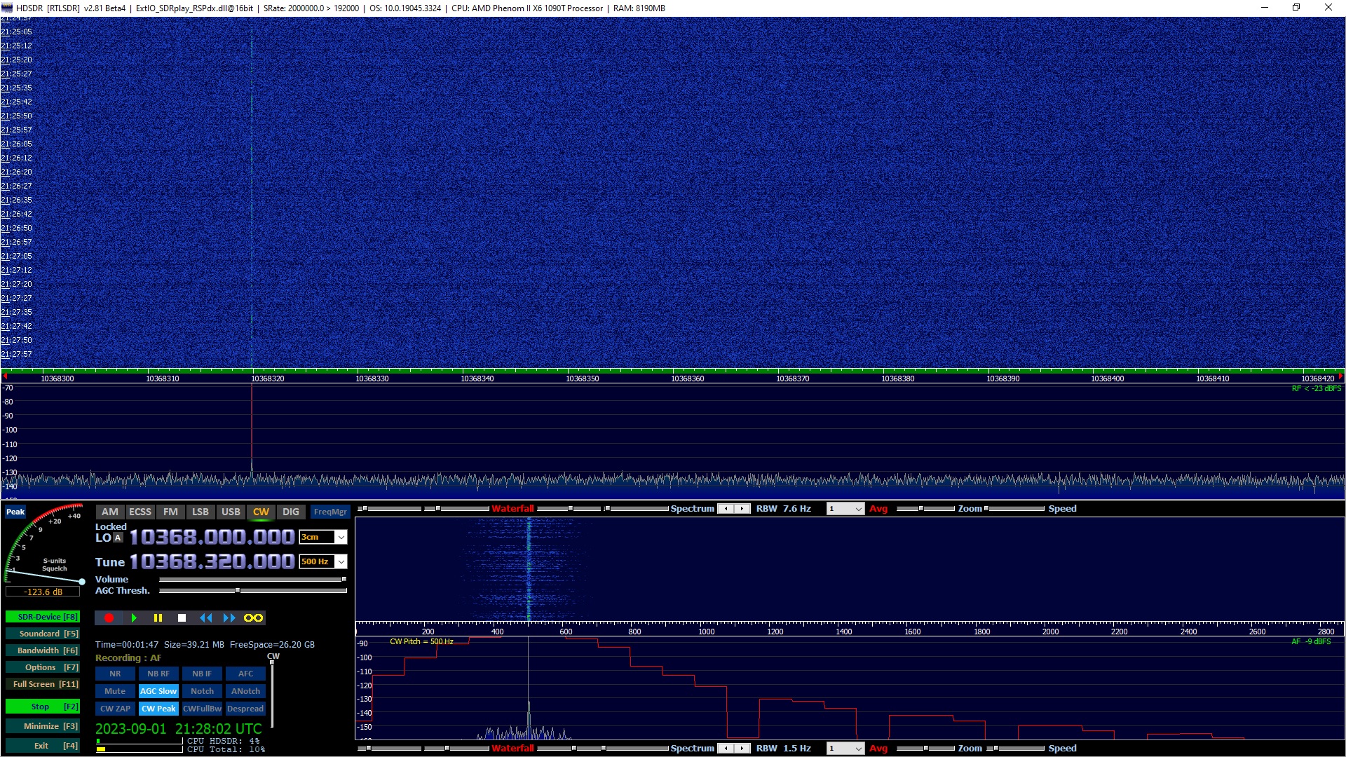
Tropo! I have not been monitoring 10 GHz, as it simply costs too much to run the computer. On the afternoon of September 1 I checked and found that I was hearing N1JEZ beacon about as I had often heard it for several days in July... consistently there but weak and very choppy with strong signal "flutter" making copy difficult to impossible. Here is an audio recording demonstrating that, with narrow IF filter and audio peak filter to enhance the signal:
N1JEZ/b weakLater it got stronger and I realized I was getting some real tropo conditions. Here is an audio recording made in SSB bandwidth before the peak of the opening:
N1JEZ/b in SSB bandwidthHere is a recording made near the peak of the opening, alternating between just the narrow IF filter and that plus the audio peak filter:
N1JEZ/b near the peak of the openingFinally here is a screen capture some time before the peak, showing the signal at 10 to 15 dB out of the noise:
While the 10 GHz beacon was in well, I had no tropo DX on VHF/UHF. Around the time I started getting DX on VHF and UHF, the 10 GHz beacon faded out. It returned as signals were fading on VHF/UHF. Interesting. I looked for other 10 GHz beacons many times but did not hear any. I should have looked for more distant 10 GHz beacons during the peak of the VHF/UHF opening but as this was a once in a lifetime opening on those bands I just concentrated on getting stations in the log.
Last evening I ran some one-way tests with VE2UG transmitting to see if I could hear him. We expected rain scatter using a cell over extreme northern New Hampshire but pointing our dishes toward it did result in any trace of signal. It was a weak cell, topping only about 12 o 13 thousdand feet according to the information I had. There was some rain directly between us at about the middle of the path, so we pointed our dishes directly toward each other and tried again. This produced unexpected results. I could hear Rene consistently for 10 minutes, but the note was clear and the signal was only about 10 to 15 Hz wide on the waterfall. I have not before seen rain scatter be so narrow and clear. Can it be? Also there was a rapid flutter on the signal, very much like that on N1JEZ/b when I was hearing it on tropo last summer. This rasies many questions. Is it possible I could hear VE2UG on tropo over the 356 km path with some rain in the way at mid-path? I would not expect great results in that direction because I have a small local hill in the way and high mountains further down the path. For now I will have to consider this something of a mystery. Perhaps subsequent tests will provide more information as to whether tropo is possible between us. The first photo shows the rain between us at the time. The second shows Rene's signal on the SDR waterfall.
Here is a three minute audio clip from the 10 minute test.
Beacon Update. I added a small amplifier which gives +24 dBm (250 milliwatts) output. The little amp requires -8 dBm drive, so I used a 12 dB attenuator to knock the roughly +5 dbm output of the multiplier down to about the right level. There is anotehr dB more more of loss in the bandpass filter and cables. I also did some work on eliminating key clicks. I have them down below the level of the phase noise, so any further reduction would be meaningless.
I did a beacon video update and a video about eliminating key clicks.
Today we had some good rain scatter. I heard VE2TWO/b, N1JEZ/b, KA1UAG/b, KV1J/b and saw an unkonwn signal around 10368.309 that was too weak to copy. More interesting was a test with VE2UG. At the time I was not able to hear any beacons but Rene's signal was perfectly readable on rain scatter. Having a dish with a lot more gain than beacon antennas probably made the difference. What is even more interesting is that once again I wondered if I was hearing him on tropo or troposcatter. I was rocking the dish back and forth to see where the best signal peak was. There was a rain cell about 4 degrees south of my direct heading to Rene that produced the strongest rain scatter signal. But when I pointed direct toward him, the note cleaned up noticeably. It seemed to have a T9 component mixed with the hissy rain scatter. I still have no idea what is possible from here on tropo or even just flat band conditions, but these tests raise questions. It might be just rain scatter with very little spreading.
Here is an audio clip demonstrating the change in tone when I moved my dish.
I have my temporary "micro beacon" on the bench. You may recall from the July 10, 2023 note this beacon is kludged together from two pieces of test apparatus I built. No, that's not right. I don't currently have a bench! It is down for a rebuild of the bench itself. I have the micro beacon crammed onto the radio operating desk. Having recently noticed it was weaker than usual I brought it home to check power, adjust frequency and reprogram the message.
I don't know what I was thinking when I set up the message parameters initially. I had it send "N1BUG FN55mh" then 10 seconds key down, then a 10 second pause before message repeat. That pause was a bad idea. I depend on the beacon to calibrate my rotator which frequently has pulse counting issues. The only way I can figure out when I have teh dish pointed exactly at the beacon is to rock it back and forth, noting the "x dB down" points either side and taking half way in between as being dead on. This is hard enough to do with the constant signal variation due to moving vegetation in the path. It is aggravaving to have the pauses and not know if I have gone too far and lost it, or it's just paused. I have shortened the pause to 0.6 seconds, just enough to separate the messge from the key down period. I also speeded up the CW from 10 to 15 wpm and extended the key down period to 15 seconds to give me more time to find the edges with a steady state signal. I think any pause in a microwave beacon is a bad idea, as it can compliecate finding it with antennas having a vary narrow beamwidth.
The beacon had slowly moved down 110 Hz in frequency in 11 months of continuous operation. I think that is pretty good for an OCXO! Amazingly, I never noted any short term drift due to temperature variations, with extremes of over 100 degrees F on hot summer days to -25F in a winter cold snap. I didn't even put extra insulation around the OCXO. To be fair, other electronics in the box with the OCXO do contribute some heat. I'm using a Bliley NV47A1282 OCXO. Given that it slowly drifts down, I have set it 10 Hz high initially this time. I don't need this personal beacon to be precise but that's just how I am. I want things perfect!
Oddly, power is looking more like 7 milliwatts now. I'm sure it was 5 before... aren't I? Who knows. These are more like power estimates anyway. Nevertheless I am confident there is no major malfunction and the weaker signal lately is not a beacon fault. It is probably just new vegetation in the path.
I have been working on a beacon for the FN55MH15IQ site for about two years now. I greatly underestimated the technical and financial aspects of this project. My design goals were that the beacon be as clean as possible, GPS locked, and operate in the 10,368.300 to 10,368.400 band segment. Between phase noise, key clicks and spurs, "as clean as possible" has been a bit challenging. It is a somewhat nebulous criteria since what is possible is mainly dictated by budget, availability and knowledge factors. Phase noise is typically published for synthesizers and if not, someone has likely measured it. Key clicks seem to be mostly ignored by beacon builders, as do in band spurs. I tested some commonly available synthesizer options. If phase noise and key clicks weren't a problem, in band spurs usually were. One topology that worked was a Leo Bodnar GPS reference clock as a "10 MHz" reference to a DigiLO programmed for 1152.000000 MHz followed by a W1GHZ x9 multiplier with the last two stages keyed. Frequency choices were very limited if I wanted an easy to remember integer kHz frequency in the desired range, due to the reference clock being limited to integer Hz values. Only two frequencies were possible: 10,368.310 with a 10.000299 reference and 10,368.338 with a 10.000326 reference. With new beacons coming on the air all the time and it taking so long to finish this build, that was not a desirable situation.
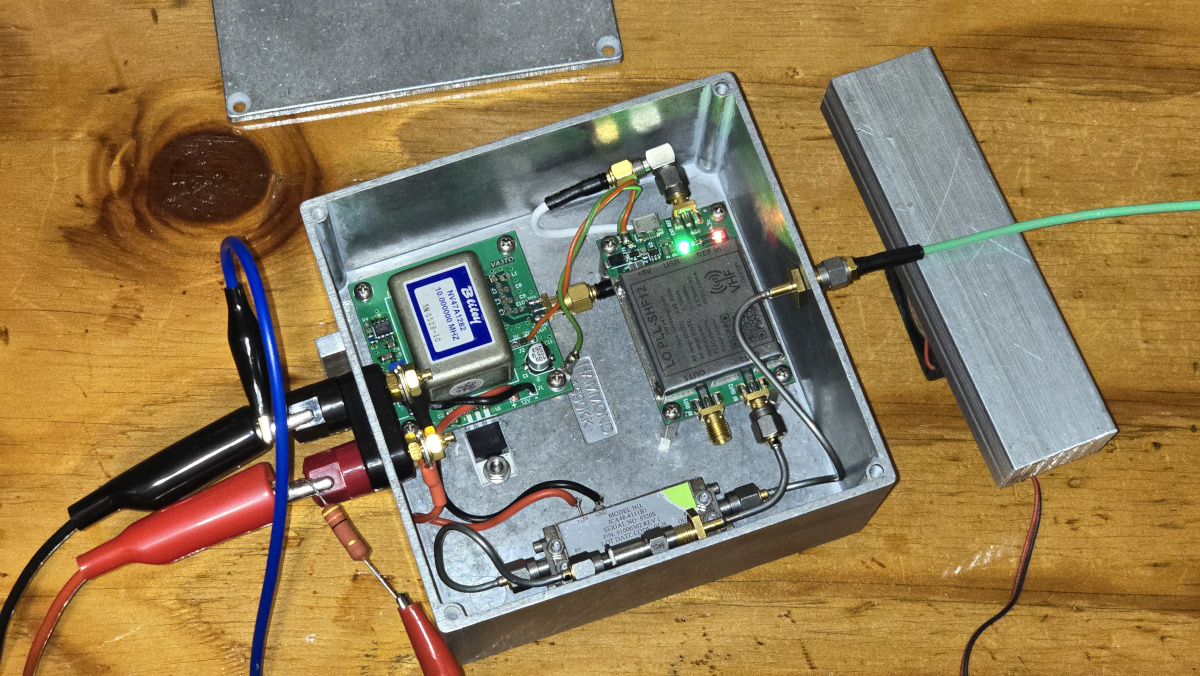
The recent introduction of the Leo Bodnar LBE-1420 changed all that. It is not limited to integer Hz values. I tested one to see if it could be used directly as an 1152 MHz exciter, but it had the familiar problem of strong in band spurs. However it runs clean as a reference producing frequencies just above 10 MHz. This allows complete freedom of frequency choice. For example, to generate 10,368.390 the reference is programmed for 10.00037616 MHz, or 10000376.16 Hz.
That is incorrect! There was a math round off error due to using a calculator that was not quite up to the task. The correct frequency is 10000376.1574074. The LBE-1420 setup utility accepts six places after the decimal. Rounding to 10000376.157407 results in an error that is an order of magnitude less significant than the LBE-1420 stated prescion, thus is insignificant.
This produces a clean signal at 10 GHz with no significant spurs.
Almost correct? After temporarily increasing beacon pwoer with a PA that I don't believe is suitable for long term operation, I can see some spurs that I could not before. The strongest are -45 dBc at plus and minus 200 kHz. There is a set at -55 dBc at plus and minus approximately 24 kHz and some slighlty weaker stuff at similarly close spacing. This is better than previous beacon configurations and is likely the best I can do.
I recently made a Youtube video on the LBE-1420 testing.
Key clicks are controlled by using an R/C circuit on the keying of the final two stages of the W1GHZ x9 multiplier. In order to control clicks on both make and break, I used a 10 volt regulator instead of 8 volts to supply these two stages. I was then able to add a 20 ohm series resistor and shunt capacitor to greatly reduce key clicks. The added 20 ohm resistor causes the capacitor to charge slowly on make, while existing resistors in the x9 multiplier discharge the capacitor slowly to control clicks on break. I am currently using 330 uF, but may increase that a little.
I don't have a proper setup for measuring phase noise but I believe it to be close to 60 dB down at 10 kHz spacing. I will update this later if I gain access to a better measuring method. Overall I am fairly happy with the signal quality with this beacon topology, and everything neeeded to build it is readily available.
I still have some work to do on the beacon. It needs a PA to get from +24 dBm (or less) to at least 2 watts, preferably closer to 5 watts if I can get it. I had wanted to include an output band pass filter and isolator but might leave those out due to budget constraints and availability. I also need to build a mounting arrangement for the slot antenna and come up with a suitable radome. I have been trying to test various radome materials for RF losses, but keep running into problems getting stable measurements due to signal reflections. This is a nightmare at 10 GHz! I have one or two more things to try and will post an update if I get anywhere with the testing. I also need to work on the code for the Arduino beacon keyer. I plan to add internal and external temperature sensors and embed readings into the beacon message so I can evaluate thermal peformance.
Meanwhile I got tired of waiting for this costly project to be completed and threw together a 250 milliwatt "quick beacon" using a VHF Design board, OCXO reference and a small PA. This is what I consider a "dirty" beacon with inferior phase noise and key click performance but I will put it on the air temporarily while I continue to work on the big beacon. One motivating factor was that new tree growth is making the signal from my little 7 milliwatt kludge beacon running on an indoor antenna increasingly weak at my station. I need that beacon to recalibrate my rotator frequently. Quick beacon will be able to be installed on the tower where it has line of sight to me. Being line of sight and higher power opens up the possibility of it being too strong to use for that purpose, but I will deal with that when and if necessary. More power and unobstructed view of the horizon should open up new areas for discovery and fascinating experiences such as rain and snow side and backscatter, reflections from towers, etc.
Quick beacon overheated during extended bench test and burn in! It is a small box but power dissipation is only 11 watts. I was in disbelief when it got too hot to comfortably touch even for a second or two and the OCXO ran off frequency due to it being too hot to self-regulate! I thought heat radiation from the diecast box would keep it cool enough. Wrong! I am currently ordering materials to add a large heat sink which will be on the north facing exterior of the outer weatherrpoof box (not shown in the photo). Watch for future updates on that.
For now I will have no choice but to use the WA5VJB LPDA antenna for quick beacon. It would be nice to get another slot antenna, maybe a bit smaller than the one I got for the big beacon, but currently I cannot afford that. Quick beacon itself was very low cost since it mostly used things I had laying around or could get very cheaply. Thanks to VA3TO for helping with a PCB for the OCXO.
I might have heard and seen my first aircraft scatter signal from a beacon today. I was listening to VE2TWO/b on extremely weak rainscatter. There were no rain cells along the path according to rainscatter.com, but there were a few small patches of rain, probably too light and too low to be identified as cells. I had a very weak, narrow rainscatter signal from the beacon. Several times I saw on the AF waterfall, and weakly heard, a second signal from the beacon swishing rapidly downward in frequency. In each case it persisted for only a few seconds. I am not claiming this was aicraft scatter but at the moment I do not know what else it could be. Here are two examples. I have several more, including some that persisted longer with slower frequency shift. Ignore the badly drifting trace lower in frequency on the RF wterfall in the second example. That is Quick Beacon which I had just switched on for a test in the shop. It's OCXO had not warmed up yet.
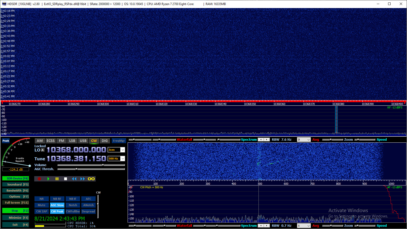

QB (Quick Beacon) morphed into a 1.5 watt beacon which just concluded a five week continuous run test on the bench. All it needs is the antenna and radome to be mounted and it will be ready to install on the hill.
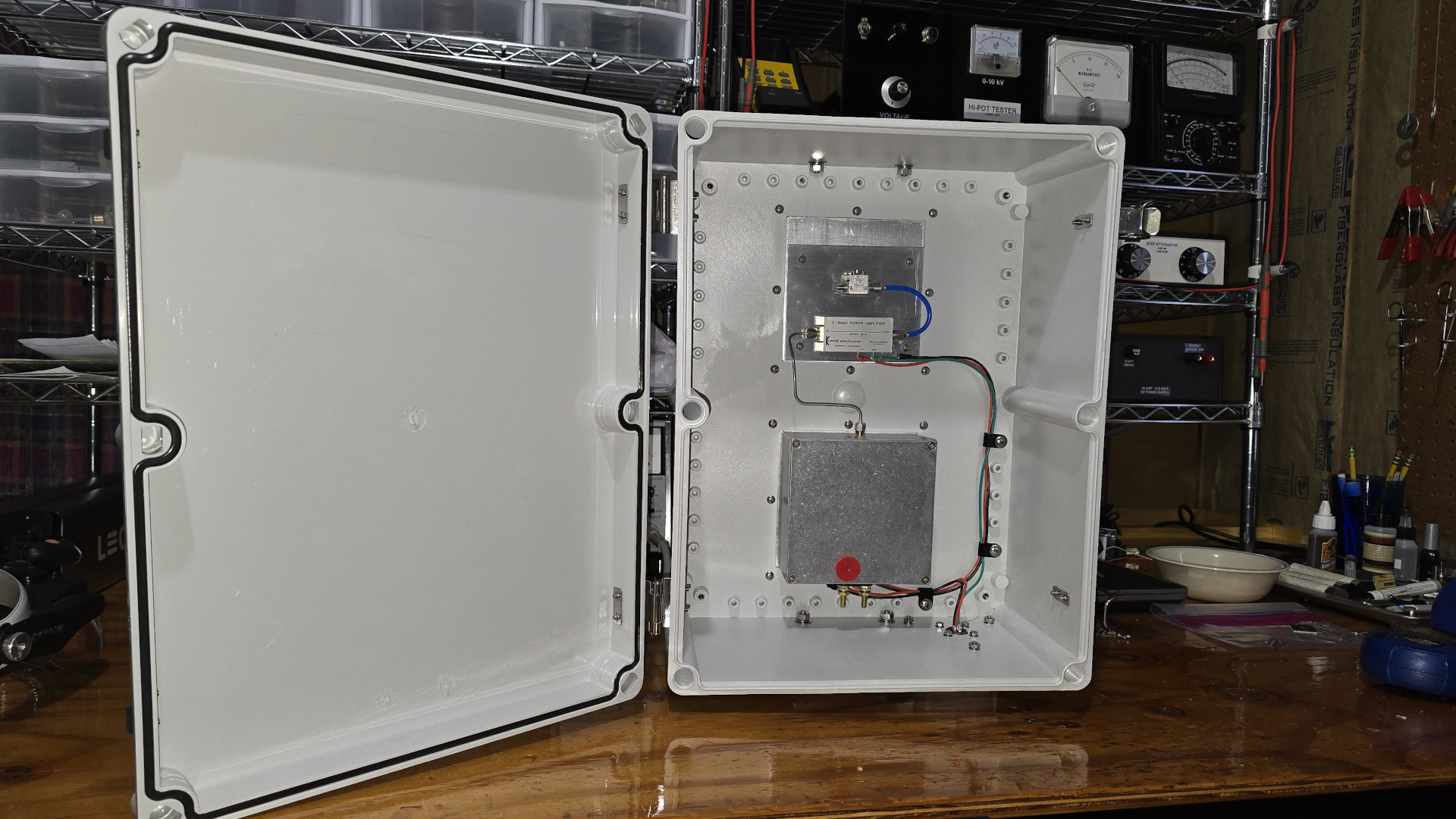
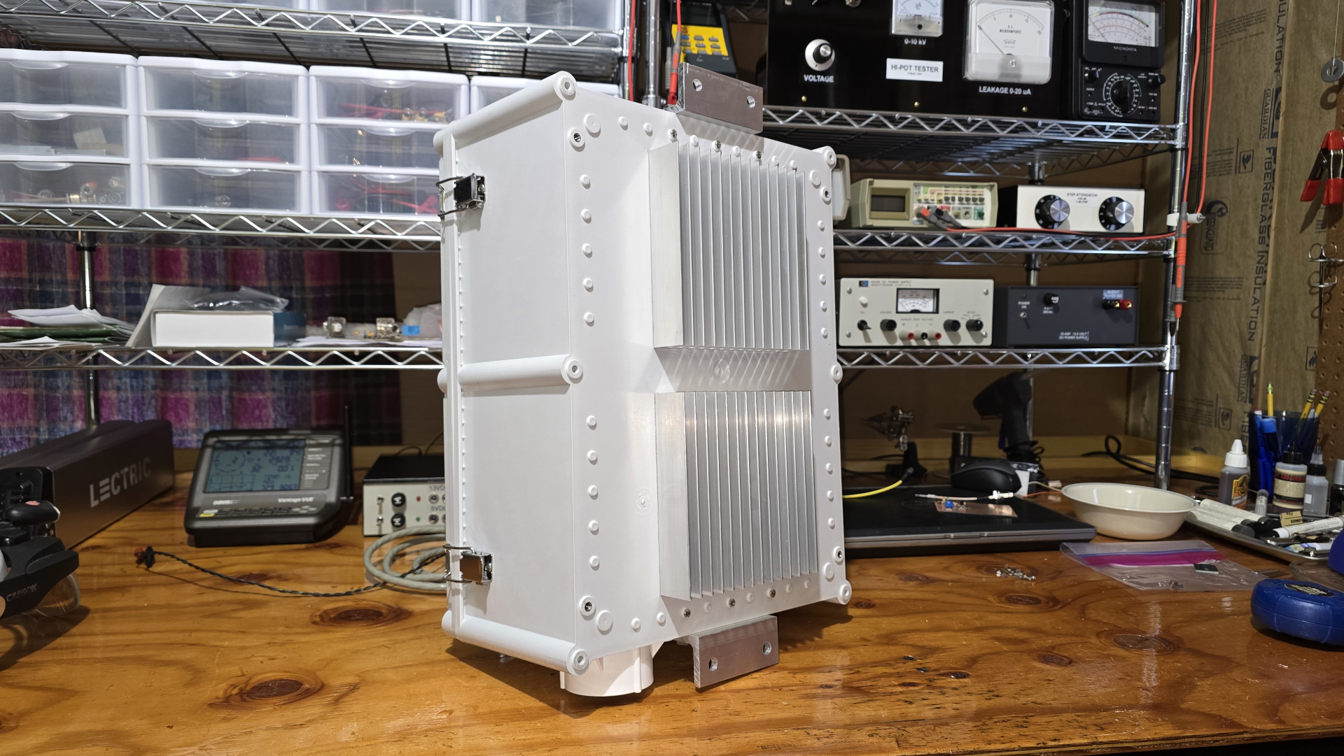
My 10 GHz journey has ended, at least for now. I severely underestimated the challenges of assembling a 10 GHz station in a fixed location where the tower is 250 feet from the operating position and 100 feet tall. Running power and control to the system would cost far more than I realized. There is no end game since I am unable to coordinate QSO attempts by phone which as far as I can tell accounts for 99% of 10 GHz attempts.
10 GHz nearly ended a 45 year passion for building. I had never before experienced anything so utterly frustrating. I evidently lack the skill (and quite probably eyesight) for microwave circuit assembly. I definitely lack tools and knowledge for fabricating mechanical parts. I finally admitted I was just throwing away money on fruitless efforts.
I am very disappointed and discouraged. I am sure I would love 10 GHz operating if there were a path to success. This is the first time in nearly 45 years exploring various facets of ham radio that I have abandoned a jourey before getting operational. I realize failure can be part of the road to success, and I don't mind failing occasionally. But this has been a constant money drain with no real progress.
I would still like to get QB up and running at the hilltop site, but until I can afford to hire a machine stop to fabricate antenna mount and radome I will not waste further time or materials on it. There are many things the money would be better spent on, including needed repairs to my home.
I'm back! Thanks to a very generous contribution by North Texas Microwave Society the Quick Beacon Project is back on my bench. QB will be upgraded to GPS frequency locking (no additional coast since I have the parts needed) and readied for installation. Power cable and a few additional bits and pieces have been ordered.
Since my Agilent E8285A died, I created a poor man's 10 GHz spectrum analyzer using stuff I already had... a Bullseye LNB and SDRPLay RSPdx receiver. I didn't take photos but there are two vidoes about the project on my YouTube channel: 10G Poor Man's Spectrum Analyzer and 10G Testing and Optimizing the 10 GHz Poor Man's Spectrum Analyzer.
There is some interesting 10 GHz propagation today. W1FKF is testing a new beacon at his home. The path to me is approximately 290 km. I was able to decode the beacon on Q65-30D for several hours and was also able to copy the PSK CW message for long periods of time. I am not entirely certain of the propagatio mechanisms involved. There was light rain in the vicinity of the beacon but nothing mid path and nothing anywhere near tall enough for my dish to see it. At times there was minimal freqeuncy spreading of the W1FKF signal. At other times it was nearly 100 Hz wide. My guess is the primary propagation was tropo with freqeuncy spreading and possibly some assist by rain scatter.
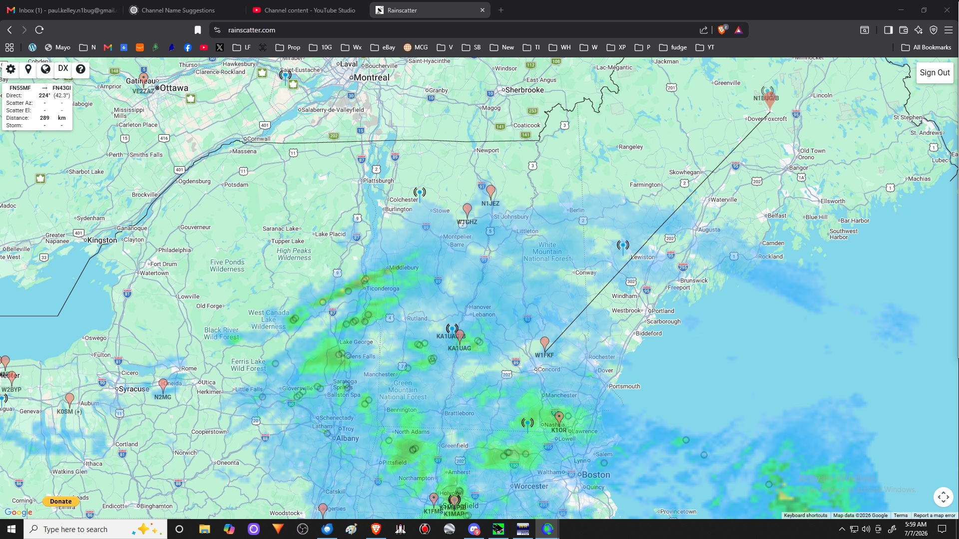
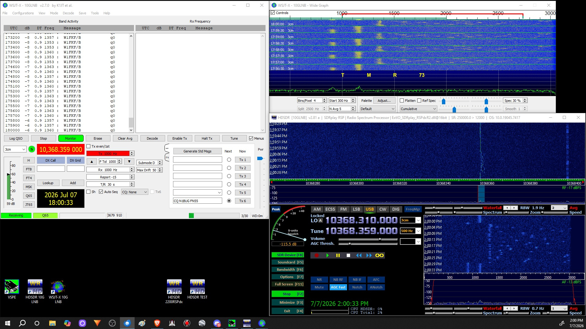
Here is a short audio clip, narrow bandwidth and here is a wide bandwith sample.
Quick Beacon is on the air!!! I think it was misnamed though. This was anything but quick. Thanks to North Texas Microwave Society for making it possible to complete this long term project! The following photos are: QB mounted on the tower; QB GPS antenna:
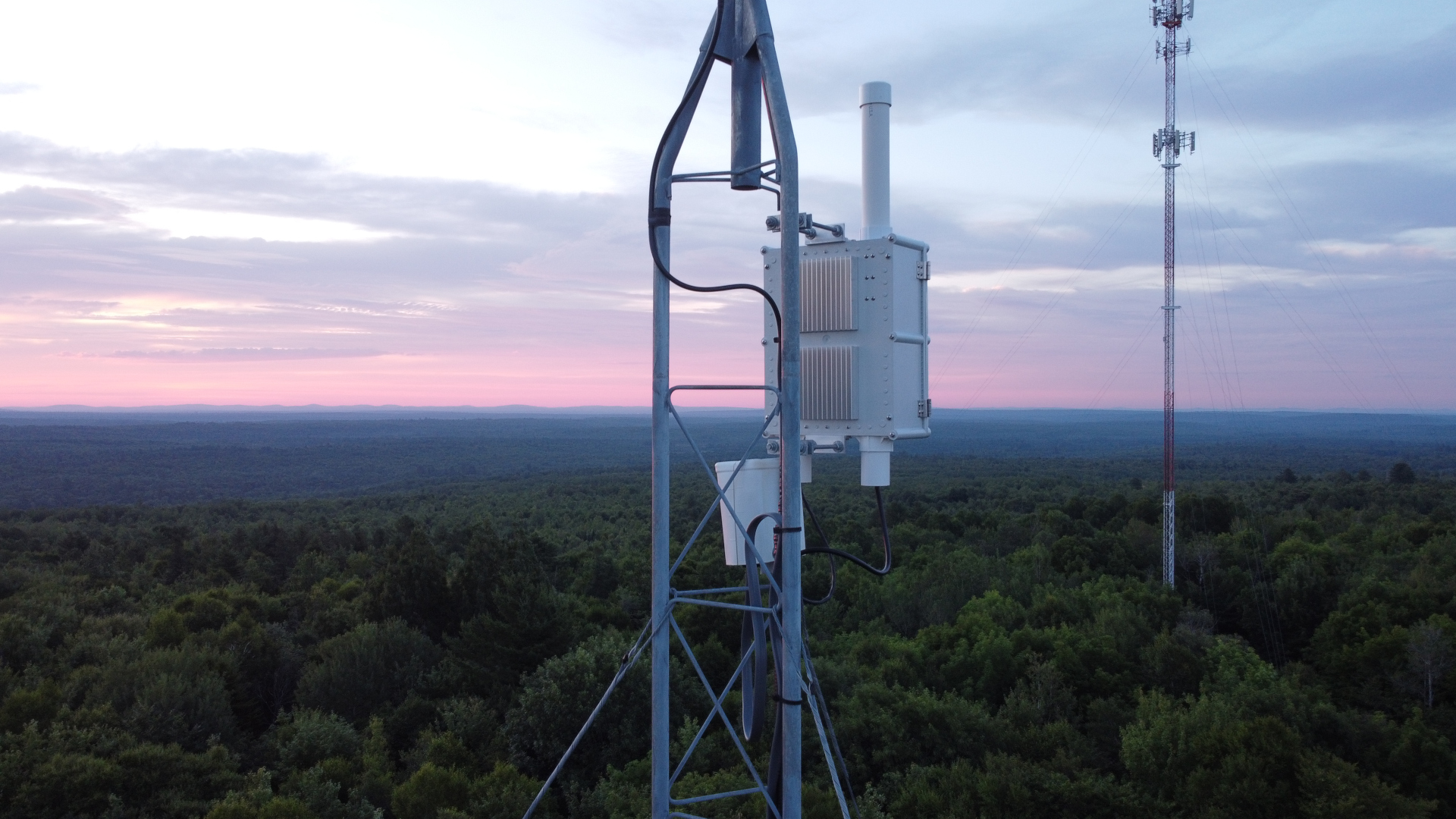
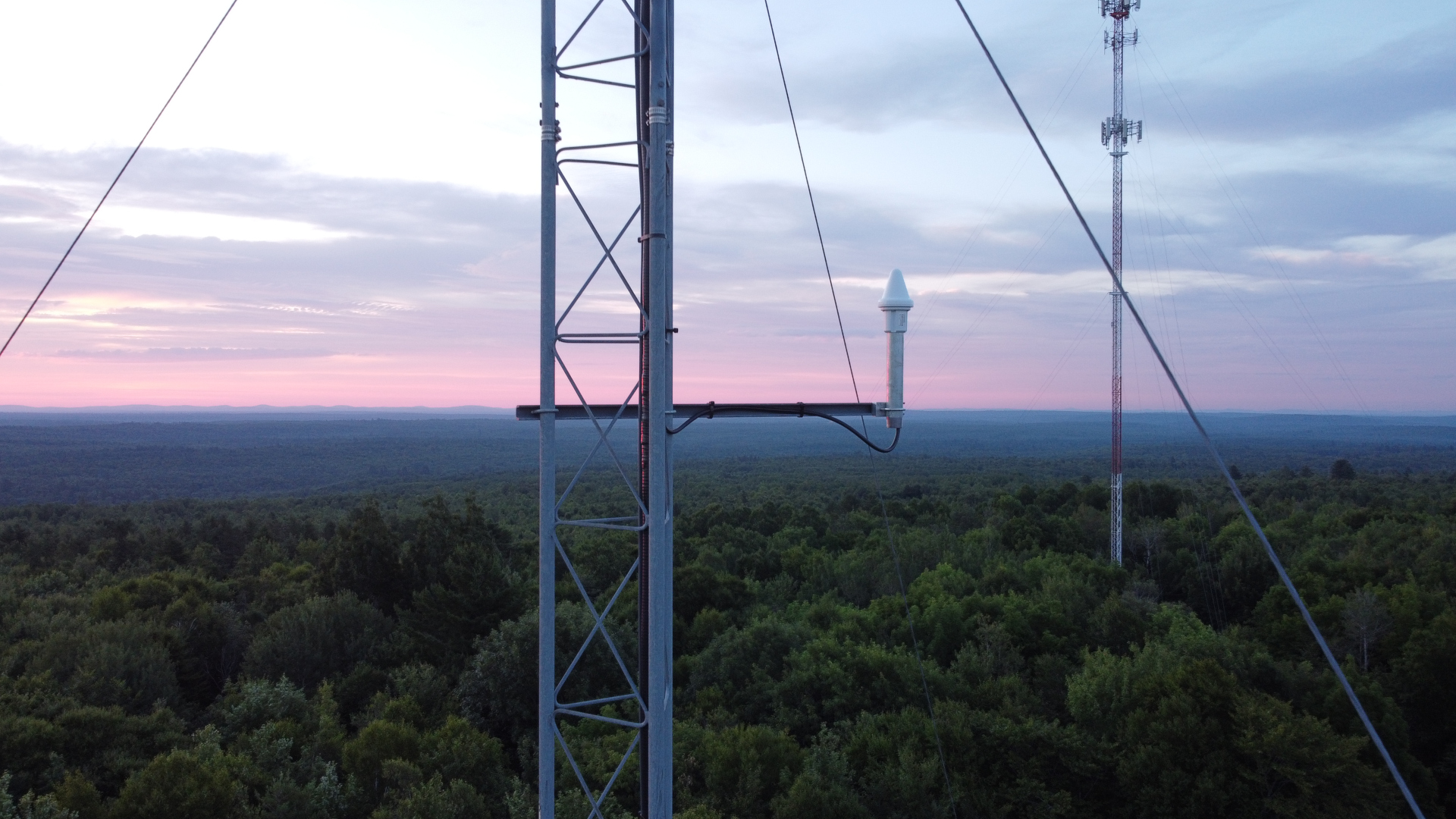
QB view southwest; QB view west; QB view east; QB view southeast:
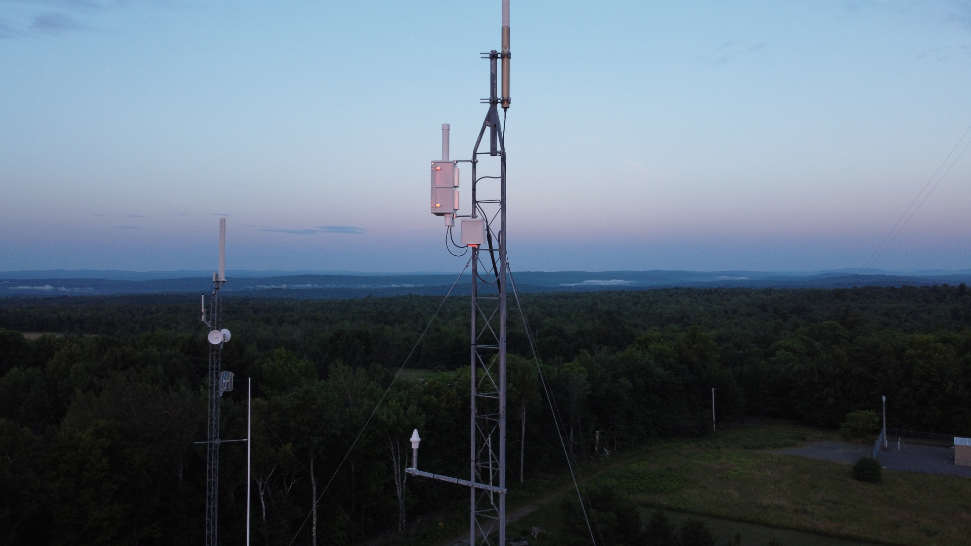
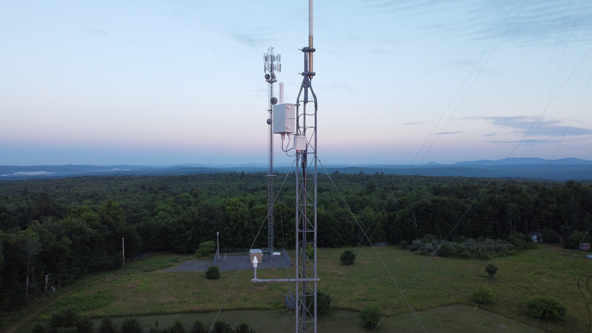
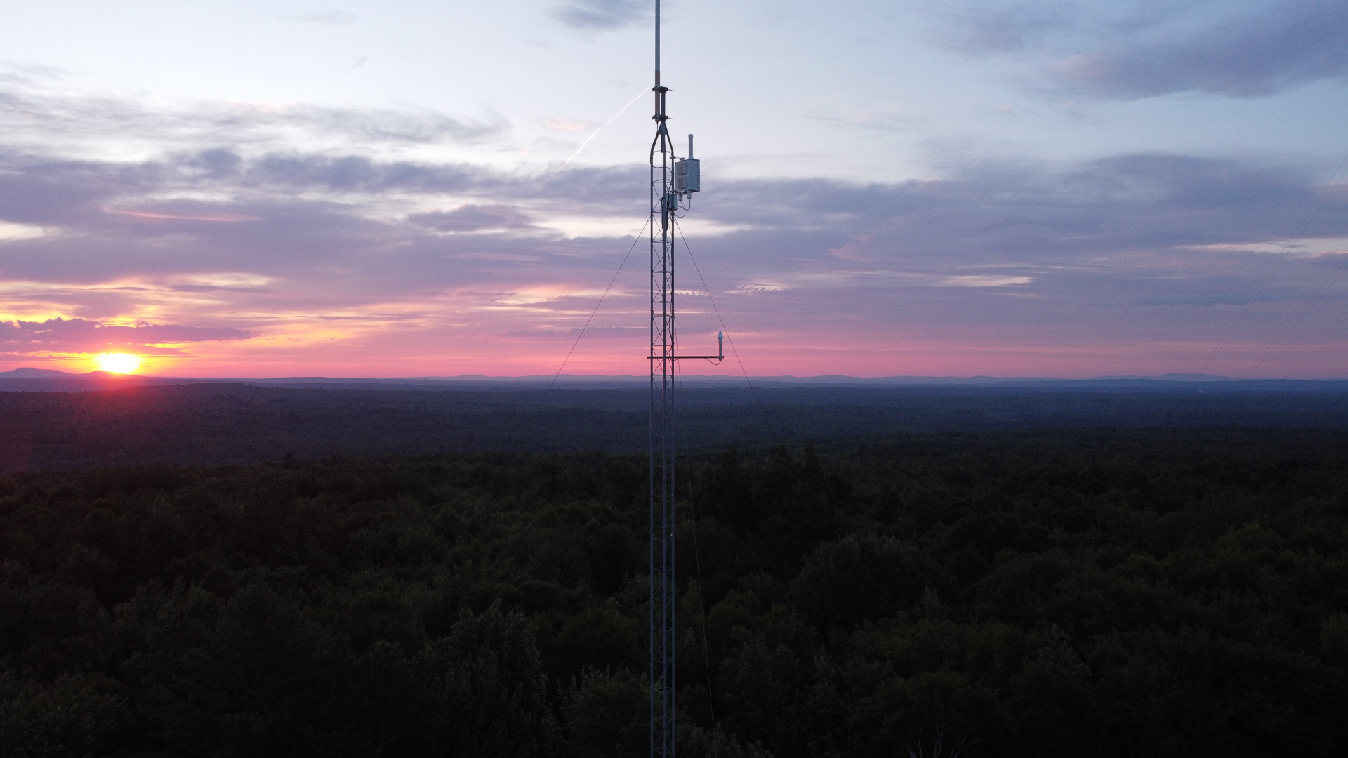
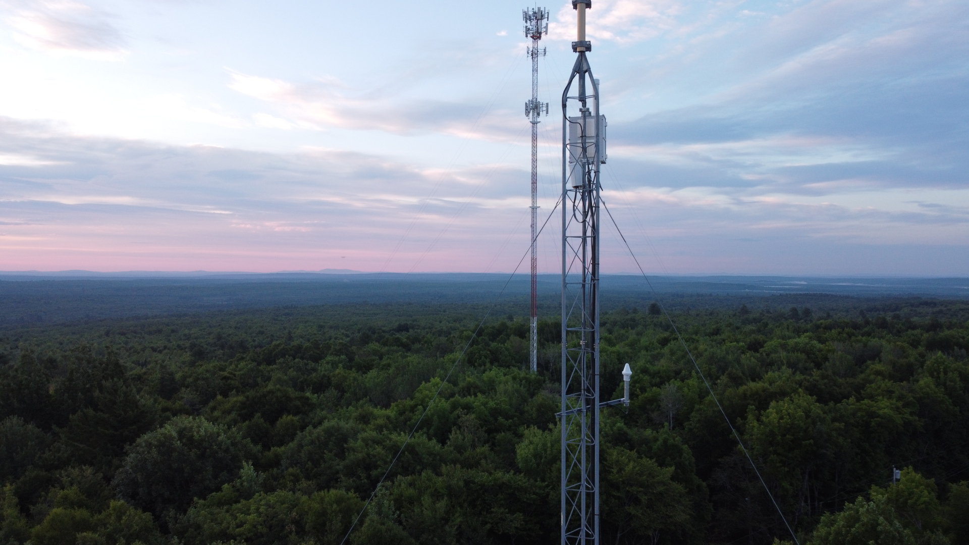
There is a TouTube video about installation of the beacon.
The first reports of Quick Beacon reception are in! Here are short video clips of its reception by K1FMS approximately 466 km (290 miles) southwest and VE2ZAZ approximately 536 km (333 miles) west. VE2UG and W1FKF sent screen shots showing QB visible.
Also during the night I had good reception of N1JEZ beacon on what appeared to be tropo (troposcatter?) over an obstrcuted 314 km (195 mile) path. Here is a narrated video and audio clip.
What an exciting night! Last but not least, I had solid copy on W3CCX beacon, 694 km (431 miles) to my southwest via rain scatter for over two hours! Amazing from here in the valley! My location may not be as bad as I thought for 10 GHz! Here is a narrated video and audio clip.
Last update July 20, 2026