
Updating a Swan TV2 Transverterby N1BUG |
Click on any of the images on this page for a larger version
Thanks to K1WHS I used a Swan TV2 transverter for all of my 2 meter SSB/CW operations (including EME) from 1998 to 2007. One of the big problems with the TV2 is local oscillator drift. I had taken the orignal LO and mounted it in a small aluminum box above the chassis, adding a proportional heater circuit which ran continuously even when the transverter was not in use. Even so, frequency stability was disappointing. In the later years of use, I also had problems with the open frame T/R relay, which would create "static crashes" on receive. I cleaned the contacts but the problem soon returned.
By early 2009 I was itching to get back on 2 meters. I still had the old TV2, which had been modified so many times it was now a mess. When I made inquiries about a "project" transverter, WA9JML offered annother TV2 that was in better overall condition. It turned out to be a perfect candidate for minor repair and major modification. The updates include:
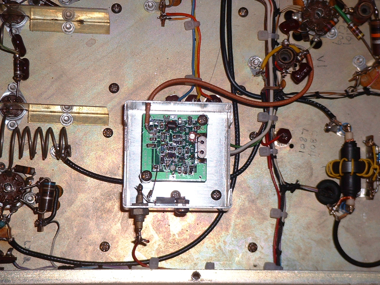 I wanted to improve frequency stability, but I knew from previous experience that would require complete replacement of the local oscillator. I also knew there was no point trying to build one; oscillators hate me! After inquiring about suitable inexpensive LO boards or kits, I was pointed to the W6PQL VHF OCXO kit. I initially had doubts about assembling the kit with those tiny surface mount components, but I ordered the kit and got a 116 MHz crystal from Downeast Microwave. After viewing W6PQL's video on how to work with surface mount parts, it wasn't too difficult to build the kit. Initially it didn't work, but the problem turned out to be a cold solder joint that I missed during assembly inspection. In order to get sufficient LO injection for the TV2 I had to change R8 to 110 ohms. As you can see in the photo, the new OCXO is mounted on the underside of the transverter chassis in a small aluminum minibox. The minibox cover is off for the photo. A short length of RG-316???? coaxial cable connects the OCXO to the junction of L802 and C101 in the TV2. This is the same point where output from the original LO was routed.
Every "stock" TV2 I have seen (four of them) presented a horrible load to the exciter used to drive it. When I first looked at a TV2 schematic I thought L202, C202, C203 was a pi network for input matching. Then I realized you can't match 50 ohms to something near 700 ohms with equal value capacitors on both sides of a pi network! Clearly those parts were there for some other purpose, if they were ever there at all. I have yet to find a TV2 with any of those parts in it. Were they removed by a previous owner, or did they not exist in the first place? They are shown on every TV2 schematic I have seen. Some (not all) TV2's had a 470 or 500 pf capacitor to ground on the normally open contact of the 28 MHz section of the T/R relay. This part is shown on some (not all) TV2 schematics, so apparently it was a production change at some point. I removed that capacitor in the interest of minimizing the level of drive required and getting a better impedance match.
My original plan was to remove the three 220 ohm resistors that are in series with the 28 MHz drive going to the transmit mixer (R202, R205, R206), so as to be able to use very low drive. That was a mistake! With those resistors removed the mixer oscillates at or near 144 MHz! I put them back and all was well again. I then built a pi network to match 50 ohms to 700 ohms and inserted it before the string of 220 ohm resistors. Computation gave values of 78 pf (50 ohm side), 1 uH series inductance, 37 pf (700 ohm side) for a Q of 5. I wound a coil of approximately 1 uH and experimented a bit with fixed capacitors at each end until I achieved a good enough match (1.1:1 SWR at 28.2 MHz).
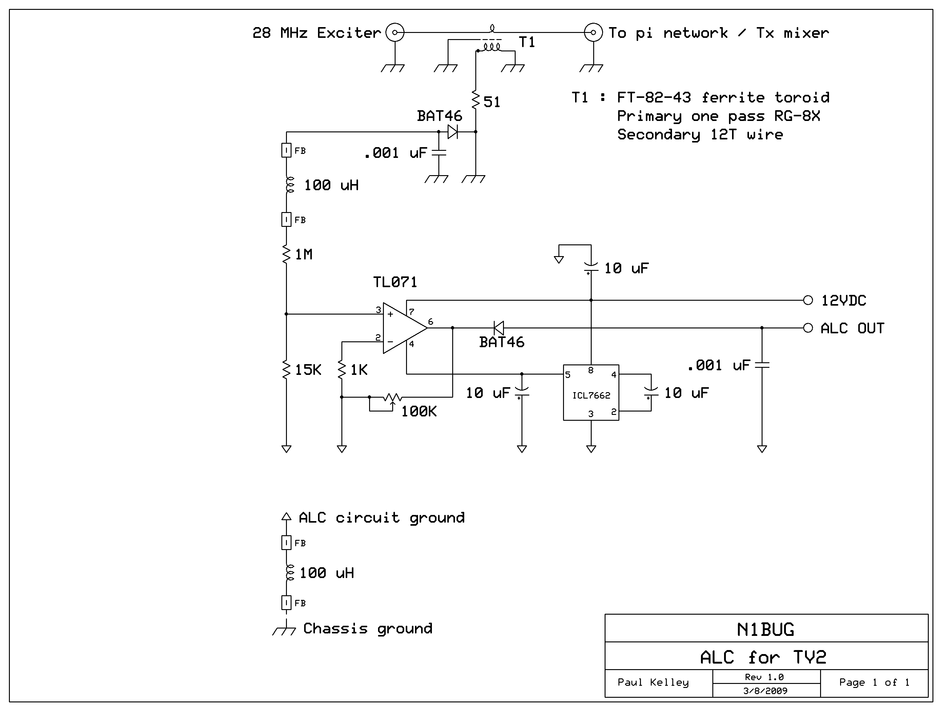
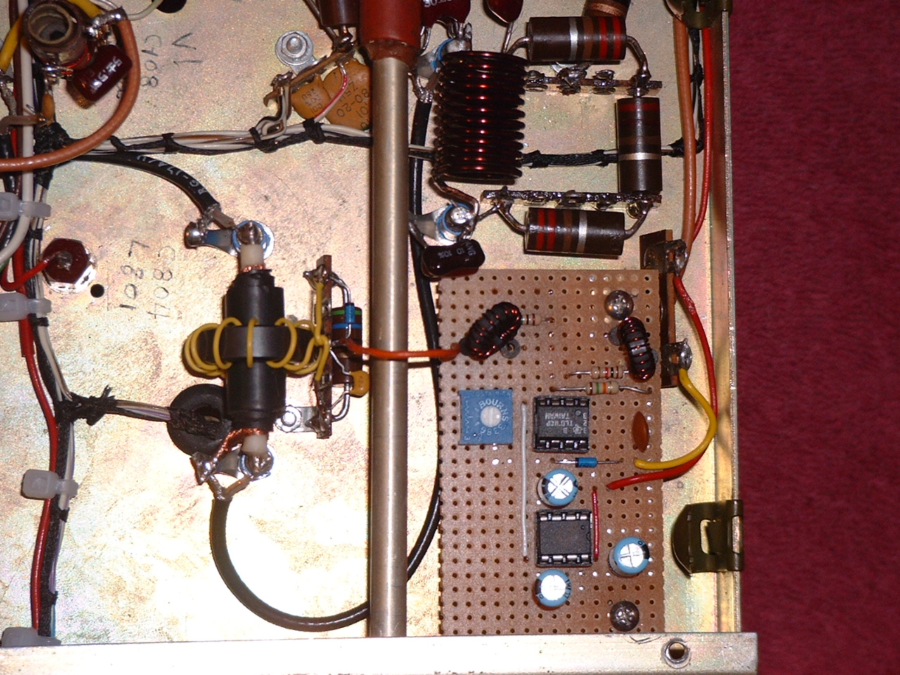 With the input configured as described, approximately 10 watts 28 MHz drive is required for full output from the TV2. I wanted a way to make sure I didn't accidentally overdrive the transverter when using it with a 100 watt transceiver. I discovered an ALC circuit by DH1DM and modified it to suit my needs for this project. The photo shows the ALC and input matching network. I did not want to sample RF at the 144 MHz output and use that for ALC. That could make tuning the transverter difficult and could result in considerble damage should a tube go bad. With a failed tube, output from the transverter would drop, causing the ALC to crank up the drive in an attempt to compensate. I didn't want that happening! So my ALC samples the 28 MHz drive level just prior to my input pi network, thereby keeping drive to the transverter at a safe level. At first I tried to sample the 28 MHz drive by means of a small value capacitor feeding the diode at the input of the ALC, but every attempt I made caused the input SWR to deteriorate significantly. After wasting two days on that, I resorted to sampling the input by means of a toroidal current transformer. I used a FT-82-43 core since that was what I had on hand. The primary is one pass of RG-8X coax through the core. The coax shield is connected at one end only since otherwise it would shield the core from the RF passing through. The secondary is 12 turns of 26 AWG plastic coated solid copper wire which I salvaged from an old piece of modular phone wire. The BAT46 diode and 1000 pf capacitor are mounted on a phenolic terminal strip near the transformer. A short wire connects to the op amp input on the circuit board. The TV2 is capable of slightly more than 100 watts output, given appropriate voltages. I set the ALC to limit drive to a level sufficient to allow for 80 watts output. If I someday build an amplifier that requires less than 80 watts drive, I can simply crank up the ALC trimmer to limit the TV2 output to whatever I need.
T/R switching in a stock TV2 is handled by means of a 3PDT relay. One set of contacts takes care of switching the transceiver input to either the receive or transmit covnverter. Another set switches the antenna between receive and transmit converters. The third set of contacts switches the medium voltage (nominally 275VDC) between the receive and transmit sections of the transverter. The open frame relay is slow, noisy, and tends to go bad after a few decades of use. The most common symptom of a bad relay seems to be "static crashes" on receive and/or erratic receive sensitivity. Cleaning the contacts doesn't always restore proper operation. Clearly this was another area needing attention.
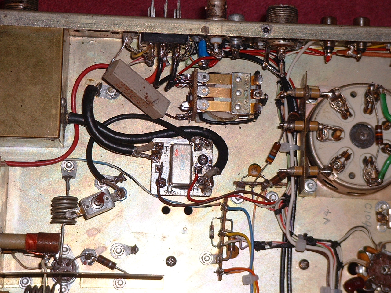 My solution to this was threefold. I was going to use a dedicated transceiver with the updated TV2, and the transceiver I drafted for the purpose had a separate receive input. Therefore I didn't need to switch the transceiver connection. I ran RG-174/U coax from the transmit section input (my ALC detector) to the "transeiver" SO-239 jack. I installed a BNC jack beside the SO-239 and routed RG-174/U coax from there to the output of the receive converter. For antenna switching, I found a small relay module in my junk box that was perfect. It came out of some old General Electric two-way VHF radio I had dismantled (at the moment I can't recall what model radio it came from; I'm trying to find out so I can look for more of them). It has a small sealed metal case relay on a one inch squre PCB, with connections labelled A (antenna), T (transmitter) and R (receiver). I mounted it near where the original 3PDT relay had been and wired its contacts appropriately. This relay is shown in the photo. Any small relay suitable for switching 100 watts RF at 144 MHz could be used. The other relay visible in the photo, which coincidentally is a 3PDT, is not used for T/R switching. Before you ask, no it is not the original relay from this or any other TV2! It is a relay I found in my junk box, and is used to energize the TV2 external power supply (I'm using a Heathkit PS-23) when I switch on the transceiver. 12VDC from the transceiver energizes the relay coil. One set of contacts is wired to previously unused contacts on the TV2 Jones connector, which in turn have conductors in the power cable that connect across the switch contacts in the power supply. A SPST relay is all that is needed here, but I didn't have one so I used what I had and just ignored the extra contacts. The sand resistor visible in the photo is 39 ohms and is used to drop the coil voltage of the power switching relay to approximately 10 volts. It was running quite warm on the nominal 13.7VDC and I was worried about it. I tested the relay to make sure it would reliablly pull in at 10 volts and it does. It runs much cooler this way.
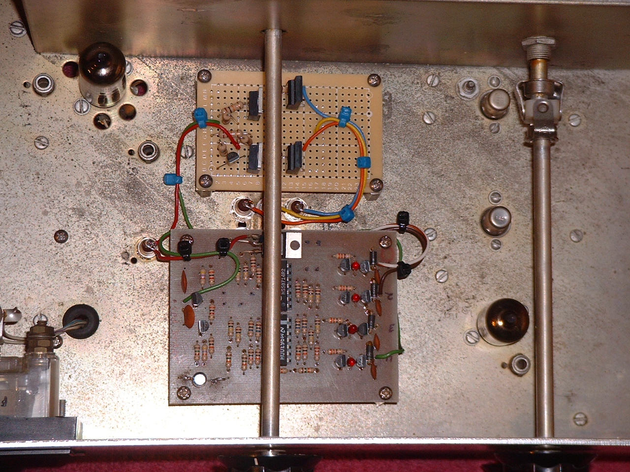 That left the question of what to do about switching 275VDC between receive and transmit sections of the TV2. I was scratching my head bald over this at first, but with some design help from VE5UF an elegant solution emerged. This function is now handled by a transistor switch. It is the smaller circuit board shown in the photo, mounted on the top side of the TV2 chassis. Connections to this and the other board are all by means of 1000 pf feethrough capacitors installed in holes that already existed in the chassis: six holes where the old crystal sockets were, and one hole vacated by removal of L801, part of the original local oscillator.
The larger board on the top side of the chassis is the added T/R time delay sequencer. The circuit is from the 2000 ARRL Handbook, and probably was in other editions as well. I adjusted the RC time constant to shorten the delay between each of the four outputs to about 20 milliseconds. The first output to switch (#1) is wired to an RCA jack on the back of the transverter for later use with an external amplifier and/or preamp. The second output (#2) is wired to the 144 MHz antenna changeover relay. The third is unused. The fourth output (#4) controls the 300VDC switch. Since no RF output can be generated until 300VDC is applied to the transmit portion of the TV2, this allows time for everything else to switch before RF is present. The sequencer input is wired to the existing RCA jack which is for transverter control by means of a ground to transmit PTT signal from the transceiver.
I suspect there are not many people interested in applying these modifications to a Swan TV2. However I will provide schematics for the home brew modules (ALC and transistor MV switch) here as they may be adaptable to other projects. Click on the schematics for a high resolution version.
ALC Circuit:
MV Switch:

Last update January 4, 2022