At one time or another most MF and LF
operators have had an accident with their antenna systems where fire was
involved. As a member of this club, I can say that its never fun
when something burns up as it usually happens in a difficult to reach
and repair location. Below are images from a few members of this
hallowed club. Check back regularly as I expect the offerings to
grow over time.
February 6, 2022 addition: VK2AN had an incident with his LF antenna
February 14, 2022 addition: G3YXM antenna tuning unit fire
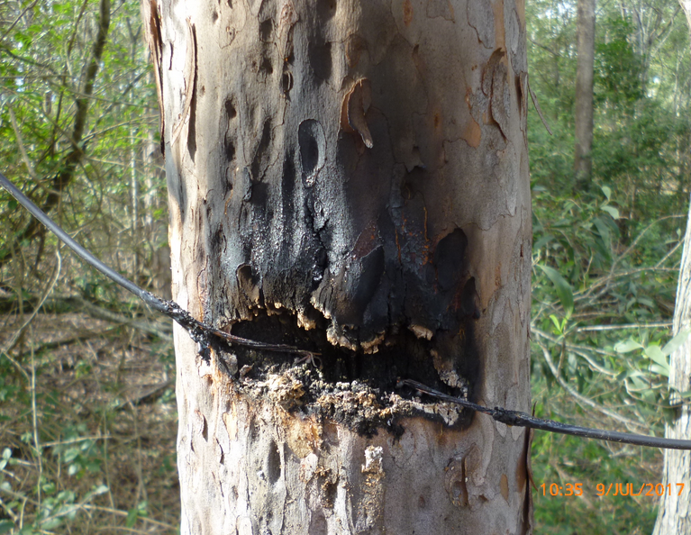
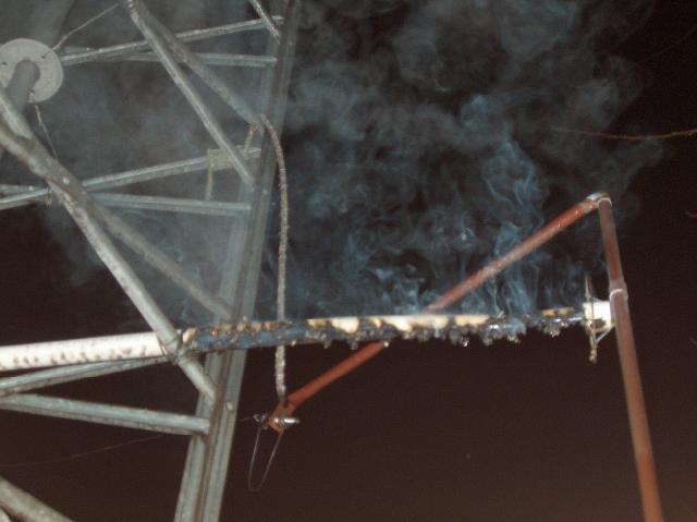
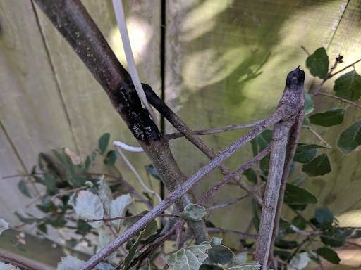
Roger, VK4YB, recently submitted this
offering which shows the awesome energy associated with 450-watts of RF
power at a high voltage point on one of his end-fed antennas. Note
that these antennas are supported at something like 100-foot above the
ground so the branch that this wire was adjacent to must have
burned up before the wire fell and did this damage.
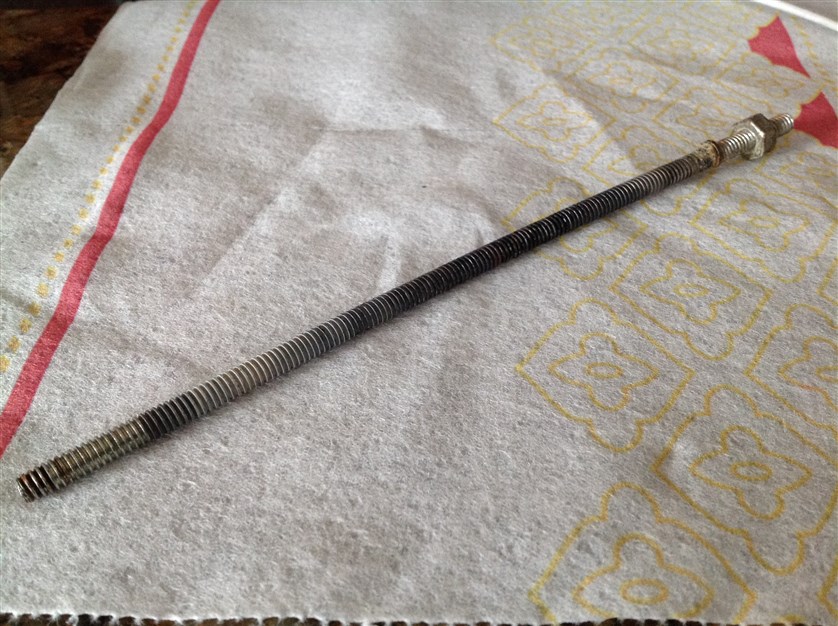
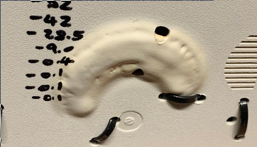
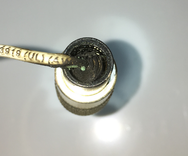
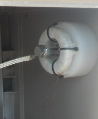
Laurence, KL7L / WE2XPQ, provided this
iconic picture a couple of years ago after a bolt (the one pictured),
got too hot after being subjected to 55-amps of RF current at 137
kHz. Laurence repaired the ATU, which has traveled all over the
world with him but the all-thread had to be replaced.
 ADDITION 10/21/2019:
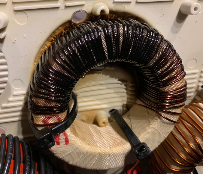
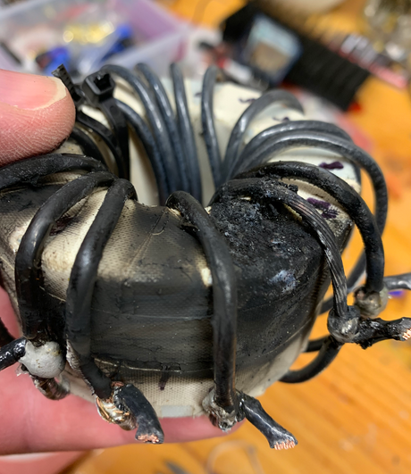
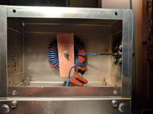
Laurence reported an inductor failure in his 2200 meter low pass filter
that had been running at power levels in excess of 1000 watts with no
problems since 2003. Note the heating that deformed the enclosure.
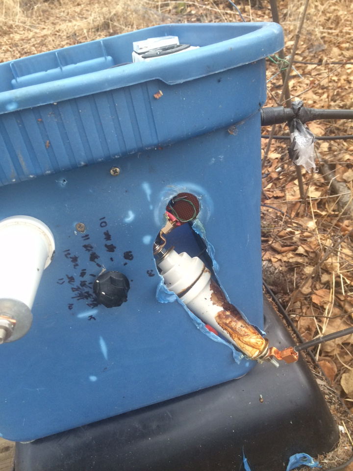
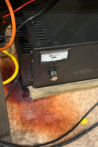
Laurence also experienced a heating
problem with a power supply that discolored a plastic carpet protector
where the supply was sitting. There was a problem with the power
supply and the transformer was replaced and returned to service.
 ADDITION 12/23/19:
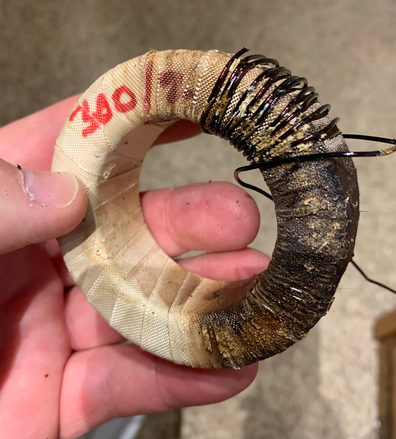
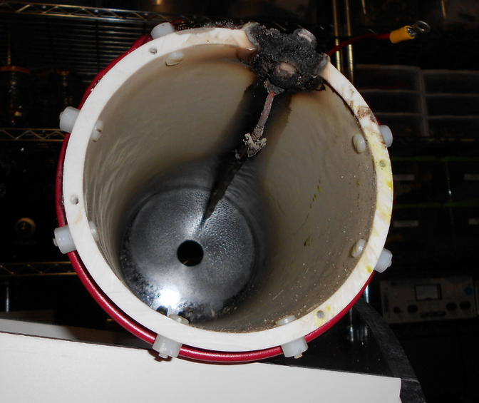
Laurence reported an inductor failure in the 2200-meter antenna coupler
(blue tub seen earlier) just days before Christmas. It seems that
there was a lot of burning and flying debris in the tub based on the
mess. Laurence believes that the ferrite is ok but he will have to
re-wrap the coil with fiber glass tape and rewind the wire, placing the
taps in their appropriate locations.
courtesy KL7L
Larry, W7IUV / WH2XGP, reports that this
is what happens when “dirty ice” builds up inside the coil form.
He indicates that the first picture is the covered coil while the second
image shows the cover removed and the full extent of the damage.
 (larger image)
 (larger image)
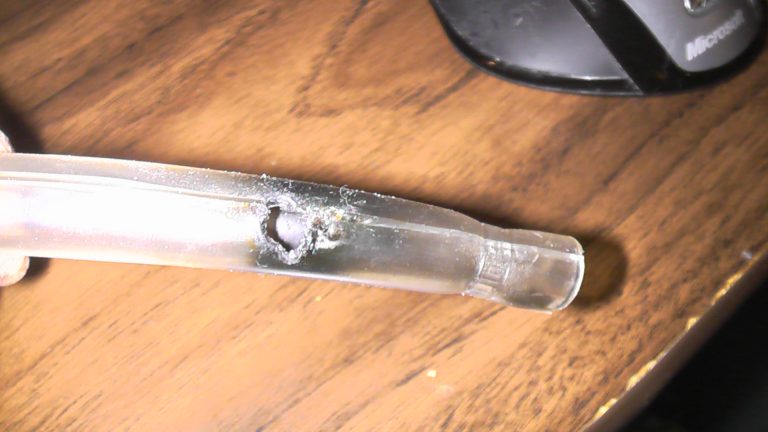
John, KB5NJD, reports this event.
"It
occurred on a very cold January night in 2014. I can only imagine
that the cold temperatures stiffened the plastic tubing I was
using as an additional layer of protection with my PTFE-insulated high
voltage leads off of the coil. The stiff tubing probably was
stressed when I moved the variometer after a CW session back to
WSPR. So much for extra protection! Fortunately the power
supplies for the amplifiers responded to the over-current conditions and
stopped the otherwise runaway event."
 (larger image)
 (larger image)
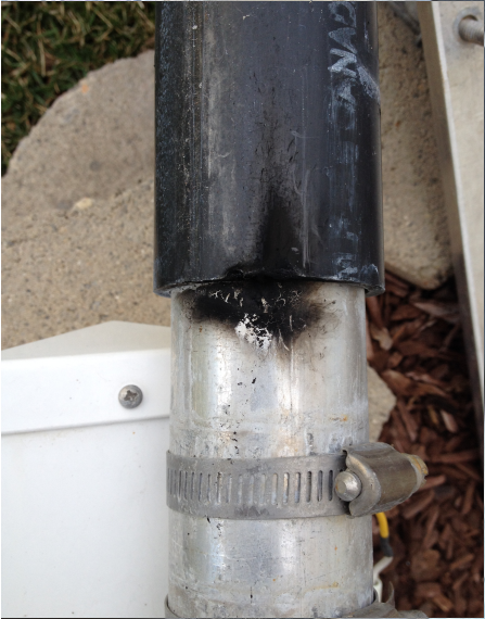
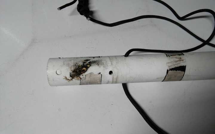
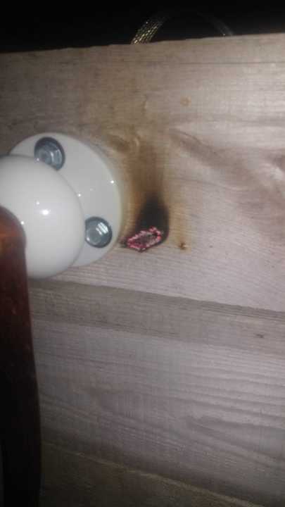
Neil, W0YSE/7 / WG2XSV, now located in Washington state, reports that
“When in Utah, I had an incident happen at the base of my vertical
antenna. I was “hot switching” the coax taps at the base of the loading
coil and things went sour. I discovered this arc-over on the back side
of my PVC “insulation”. I had to re-mount the base on a new
PVC pipe to be able to transmit again on 630 meters.”
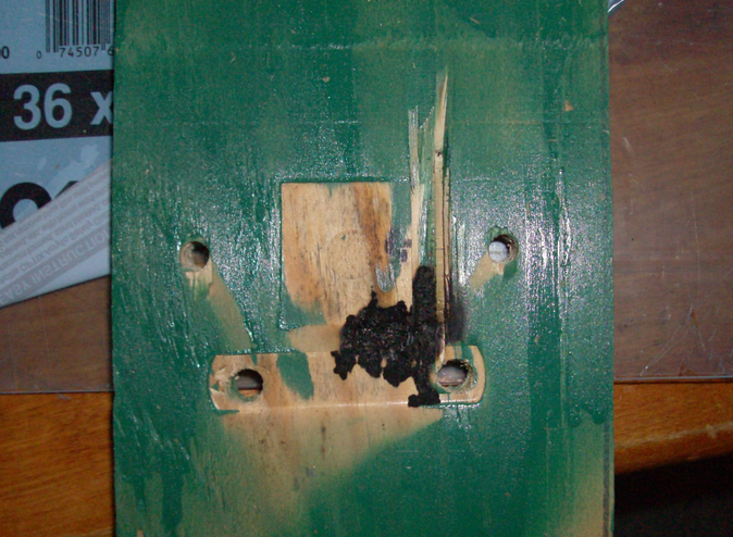
John, WA3ETD / WG2XKA, submitted this offering of one of his original 630-meter verticals:
“At one point the TX vertical consisted
of 35′ telescoping aluminum tubing, coupled to 2x, 100′ top wires on 4′
spreaders. The 2″ bottom section was insulated with a 1/8″ thick
black PVC tube, clamped to a piece of 3/4″ pressure treated plywood,
which in turn was clamped to an iron steam pipe. The PVC broke
down and burned thru to the conductive copper sulphate plywood, as
seen. The vertical now serves as my RX only vertical, no HV!”
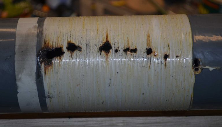
Ralph, W5JGV / WD2XSH/7, submitted a
large number of pictures that I sorted through to find three that I
thought were the most dramatic. I suppose the “take home” message
here is that PVC insulators will burn when ignited and it will generate
chlorine gas that will corrode everything and potentially kill you in a
very horrible way if you breath it. Most likely carbon tracking
started the process off due to surface contaminants on the PVC.
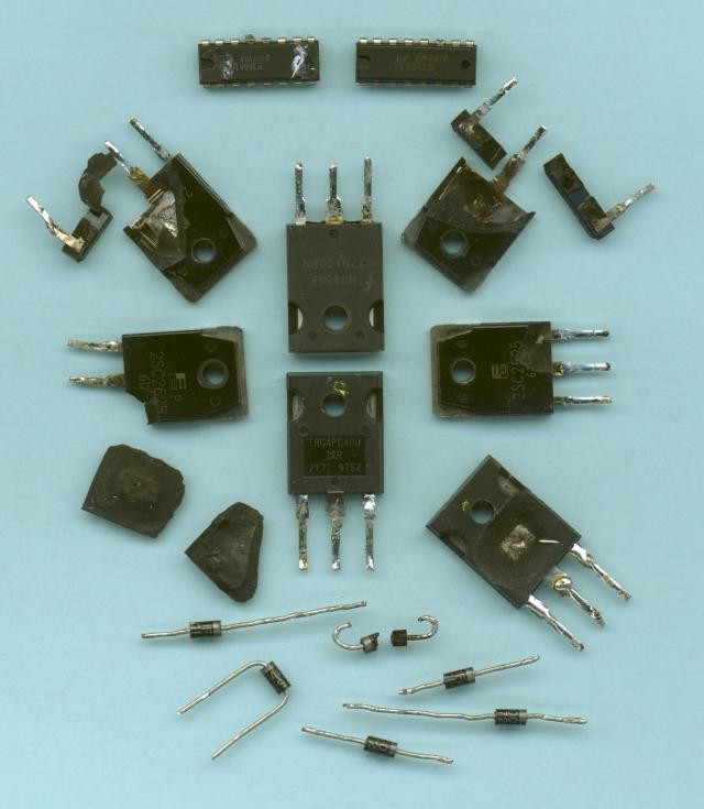
Ralph also reminds us that antennas and loading coils are not the only
parts of the RF system that can burn as semiconductors will fail in
dramatic fashion with fire, projectiles and noise. All we are
missing is scorched earth!
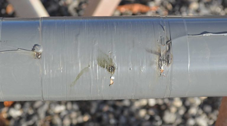
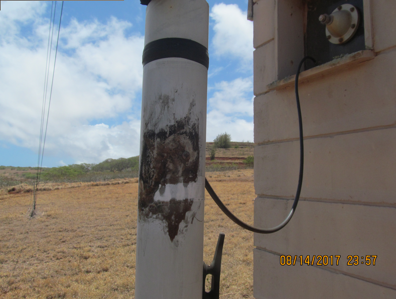
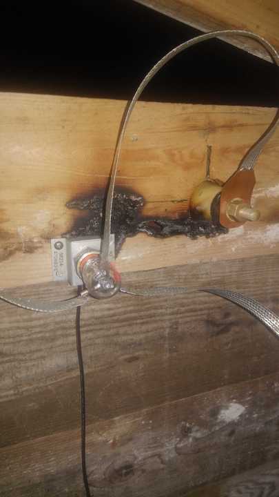
Merv, K9FD/KH6 / WH2XCR, submitted the image below of fire that came
thought the PVC base insulator of his low band vertical. Merv
explains: “This is the base of my vertical,
about 3 foot of gray electrical PVC conduit makes up the base
insulator, 3 inch irrigation pipe makes the vertical… Was tuning
and all was fine with low power, but at higher power the SWR kept
going berserk. Could not find a problem until I walked around to
look at the vertical and there was a huge black carbon trail.
Where you see the “strip” of clean in the black area is where a ground strap was before.
Fire jumped through the PVC from the vertical to the ground strap, about 8 inches.
I removed the ground strap. PVC is not the best insulator when it at a
high voltage point. I changed the tuning circuit and cleaned off
as much carbon as possible. Its ok now but needs to be changed at
some time.”
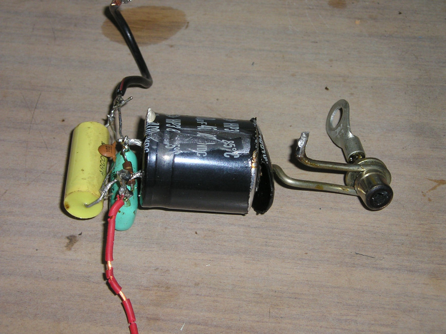
Ben, N1VF, submitted these images
showing a tree branch that he set ablaze with his vertical radiator
followed by an image of his low pass filter that experienced a silver
mica capacitor failure. While the filter failure ended Ben’s
opening night operating session, at least the explosion was
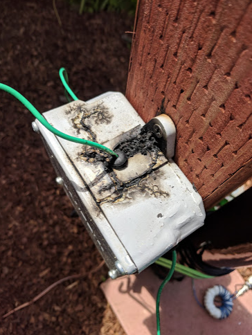
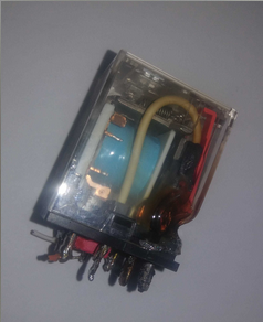
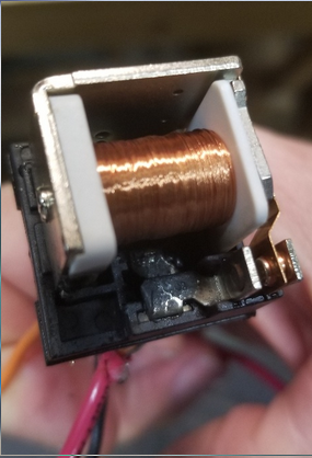
contain! Finally, Ben submitted a relay box where water had
collected on top and arced over on the case while transmitting.
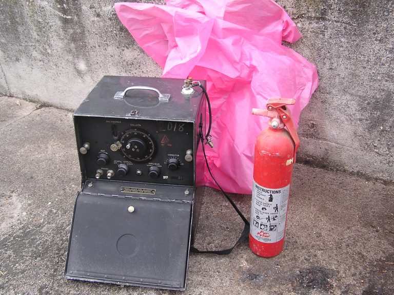
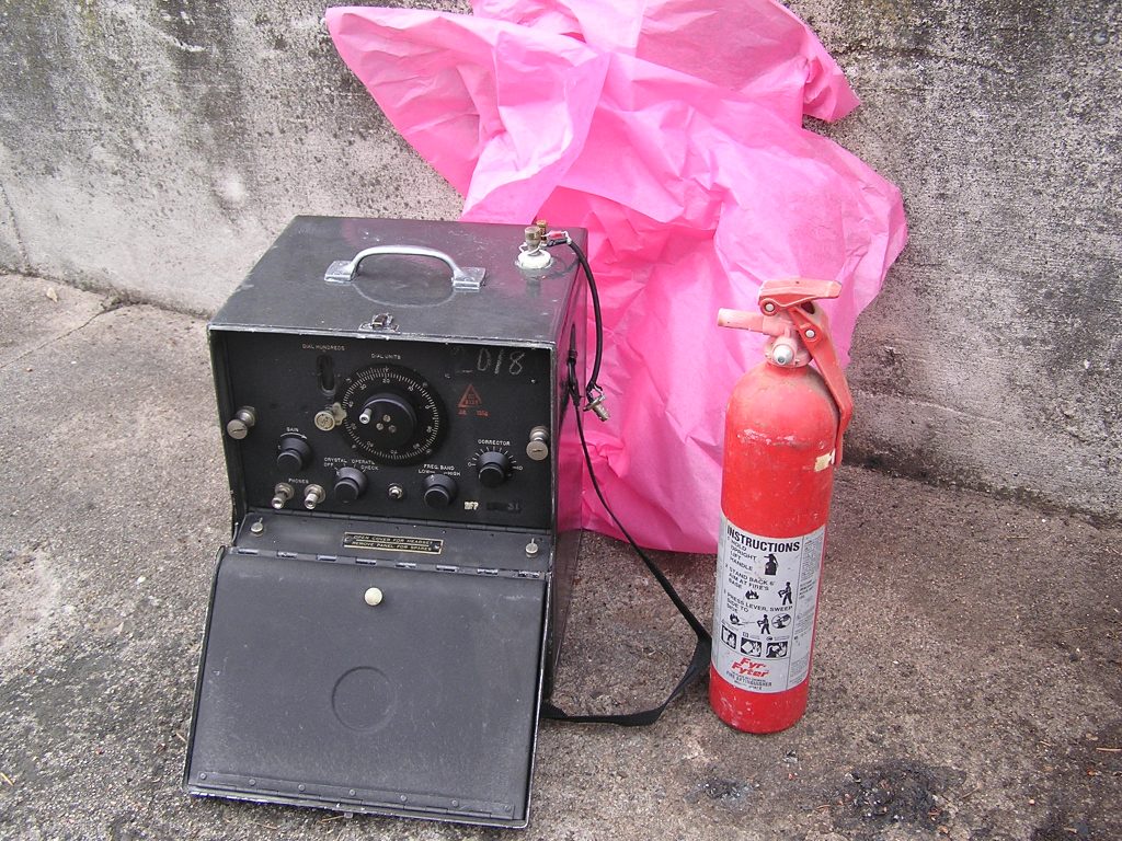
Paul, W0RW, reported that his BC-221,
capable of operation down to 125 kHz, caught fire during a routine
battery recharge. This was not a matter of simple flames, but
more like six Estes rocket motors firing at the same time as Paul
described it. The incident lead to the development of a battery
temperature monitor that he now uses while changing. The complete
story is recounted in the March 2018 issue of CQ magazine. Note
that in spite of the fantastic visual at the time of the incident, there
is not much to see so Paul staged an image that accurately depicts the
incident, minus the mess from the fire extinguisher.
 (larger image)
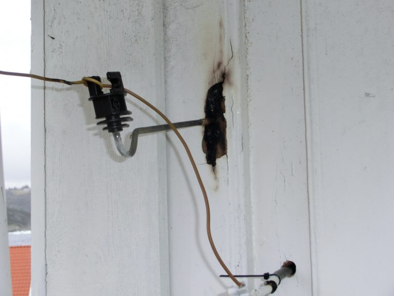
Jan, LA3EQ, submitted this gem which occurred following a storm, when “
…the
antenne lead jumped off the plastic isolator and came in contact with
metal rod on house wall. This was me running wspr on 136kHz with
60 Watts…“
 (larger image)
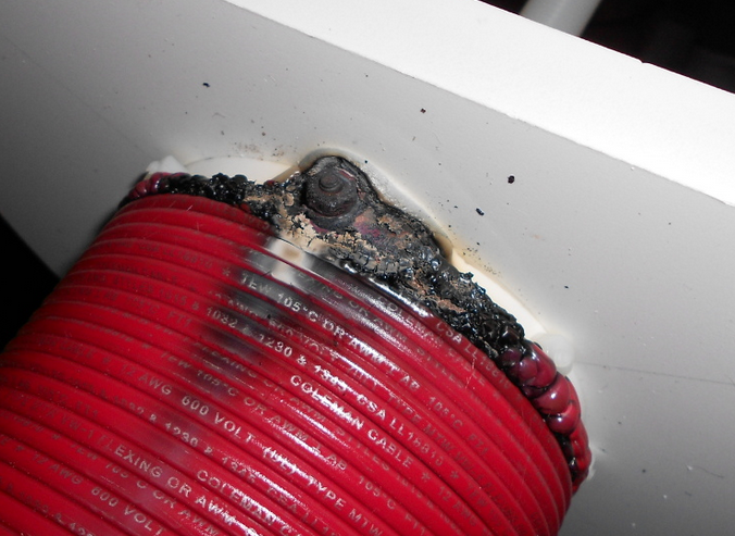
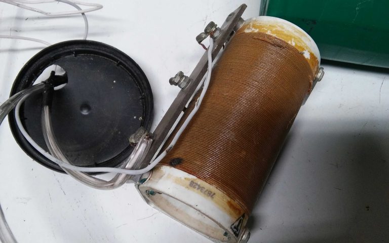
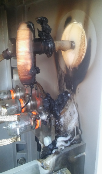
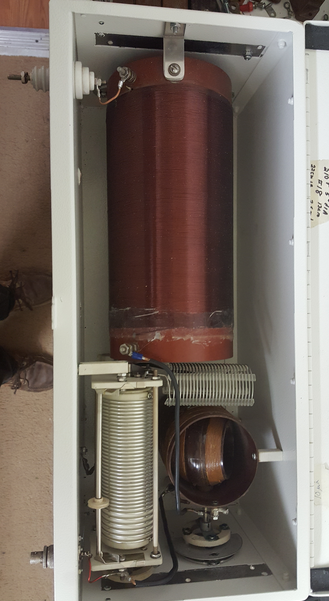
Paul, N1BUG, shows just how fast things can turn sideways:
“The transmitter had been running
~250W TPO almost 48 hours at 87% duty cycle at the time of failure.
There was no warning, or at least none I recognized. Things looked fine
on the ScopeMatch 20 minutes earlier but when I checked it again the
system was far off resonance. I shut down and went out to look at the
coil assembly. When I removed the coil enclosure cover, smoke came
billowing out!
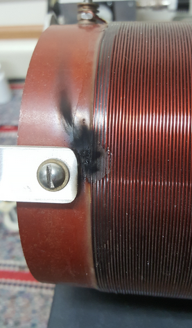
I can only speculate as to cause.
The machine screw is a pass-through connection from a wire inside the
coil form to the bottom of the coil shown. The nut on a similar
pass-through at the other end of the coil was found to be loose but
there is not yet any sign of heating on that one. I speculate this
connection loosened up and subsequent heating caused the damage,
possibly with an intermediate step of a shorted turn developing due to
heating of the machine screw. I know from other experience that a
shorted turn in the big coil causes very high current and significant
heating.”
Brandy, N1HO, took a very formal and
humorous approach to submitting his “application” for the Hall of Flame
and I could not help but include the details in their entirety rather
than simply summarizing:
“The undersigned humbly submits his
application to the Hall of Flame Club, and respectfully submits as
evidence of his stupidity and/or technical arrogance, optical
photographs of the incident as described below. A waiver of the
submission of realtime thermographic images is also requested as the
applicant does not possess, nor has realistic access to, any
thermographic observation equipment.
The attached photographs depict a
#12 THHN wire connected from top of a matching coil to a PL-259 (“UHF”)
connector affixed to the input connector (SO-239) of a 20m quarter-wave
vertical antenna. A 46 foot (14m) wire is attached to the tip of this
antenna, and is held horizontally by an avocado tree to the north. The
aforementioned wire was wrapped with approximately 3 turns of white
Scotch #35 electrical tape before insertion into the connector, where it
was soldered. However, a combination of some recent adjustments to the
physical alignment of this wire to assist with the tuning of the overall
antenna system (in the parlance of the usersof the 630m amateur band, it is
the “variometer” for this antenna), as well as the extended use of the
applicant’s newly constructed amplifier, appears to have caused this
incident. Said amplifier has a measured output of approximately 120W,
and this antenna configuration had been successfully used at the more
modest level of 25W for at least two months prior to this incident.
The applicant sheepishly admits that
the construction and use of the antenna was entirely his own “work” and
believes that no one else is potentially culpable. Indeed, he was
warned the previous evening by the designer of the amplifier that the
high current readings seen on the DC supply bus to the amplifier only
when it was attached to the antenna system described above, was indeed a
potential (pardon the pun) issue, which the applicant disregarded in
the mistaken belief that the ammeter was defective.
Accordingly, the applicant begs the indulgence of the HOFC Admission Committee and approves this application.
Sincerely yours,
Bayard R. “Brandy” Coolidge, BSEE
Amateur Radio Station N1HO
26 March 2019″

Days later, Brandy found this at the end of the top loading wire:
 02/06/20 UPDATE:
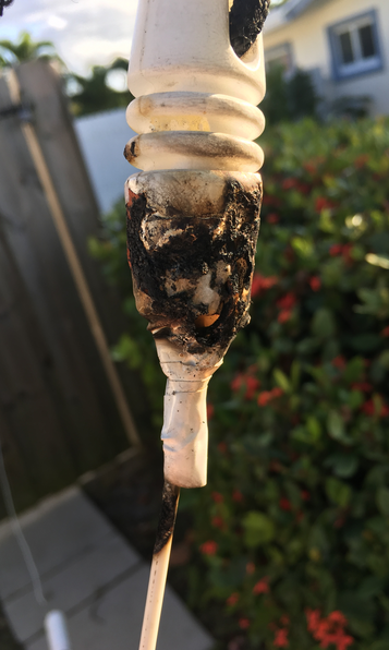
Brandy found yet another way to start a fire with RF, this time burning
through his Delrin insulator. Delrin is NOT an insulator at extremely
high voltages and when contaminants accumulate on the surface so be
careful when selecting insulating material!
courtesy N1HO
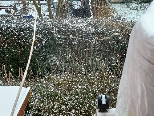
Tom, N9RU, reported that a plastic clip
was holding the radiator lead just off of the coil and wasn’t quite long
enough to avoid arcing to ground via the supporting nail and
tree. The results can be seen below.
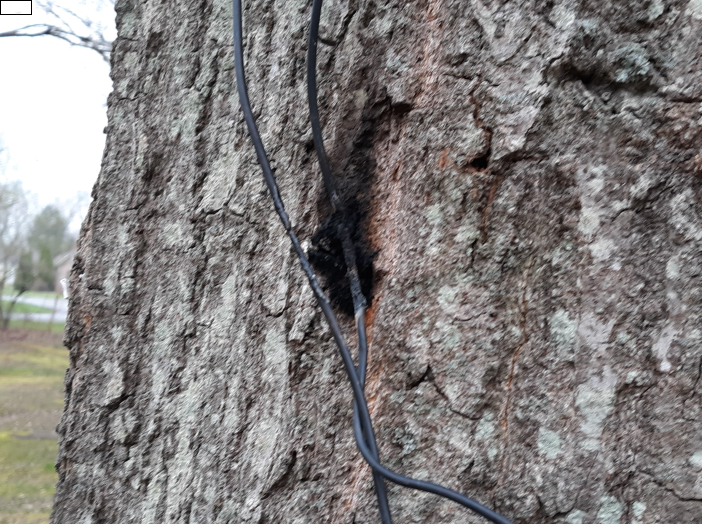
courtesy N9RU
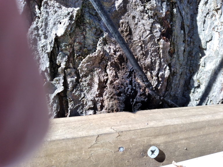
Update 3/1/2022:
Tom reports "The ice is gone and everything is dry and my SWR was still jumping around.
I found the problem. After the ice and wind, my wires have shifted and the two points where
the wire touched the tree show the problem!"
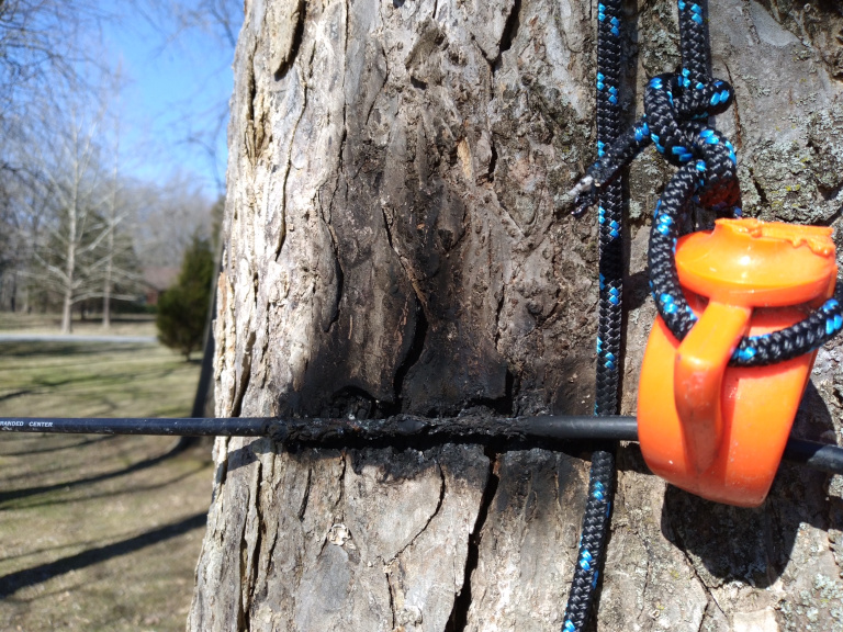
coutesy N9RU
(larger image)
curtesy N9RU
(larger image)
Mike, W3TS, submitted the following slightly afflicted Tee-top insulator, noting that it was “
…
not up to the high voltage when wet and running 100 watts to the
antenna. Tee top is now high quality glass insulators held up by
the out rigger arm.“
courtesy W3TS
UPDATE 9/13/2019:
Mike originally located a loading coil at the top of the vertical
section of his antenna and as often happens, the coil eventually arcing
at 110 watts TPO, effectively ruining the coil (look for the black spot
on the brown coil). Mike has now replaced this coil with a
variometer at the base and more power applied to the antenna, which is a
common approach for MF/LF where we are regulated by radiated power
rules.
courtesy W3TS
(larger image)
Update 9/25/2019: This didn’t take long… Submission number
three is in the books. 110 watts TPO and this BC306 vario is toast:
 (larger image)
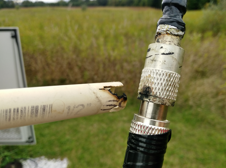
Russ, KB8U, had a a bit of excitement while in a CW QSO with me (KB5NJD) on October 3.
Russ explains:
“…My antenna had an abnormally high
SWR of about 2:1 but in my excitement I decided to blast through
it. I reduced power to about 80 watts output and made it through
the QSO without the amplifier faulting to standby.
Discretion is the better part of
valor but I just couldn’t resist (you’re only my second CW QSO on 630
meters). Today I found the culprit causing the high SWR. I
use a 40 meter dipole fed as a marconi and have the vertical element
(coax) held about a foot away from the base of the tower by some 1/2
inch CPVC pipes. Insects had built a nest inside the pipe and
heavy rain made the goo inside the pipe conductive enough so that it was
arcing to the the coax. Fortunately it was arcing where I
happened to have a PL-259 coupler so I did not even have to repair the
coax. I removed the not-so-insulating pipe, retaped the connector
and I’m QRV again.”
courtesy KB8U
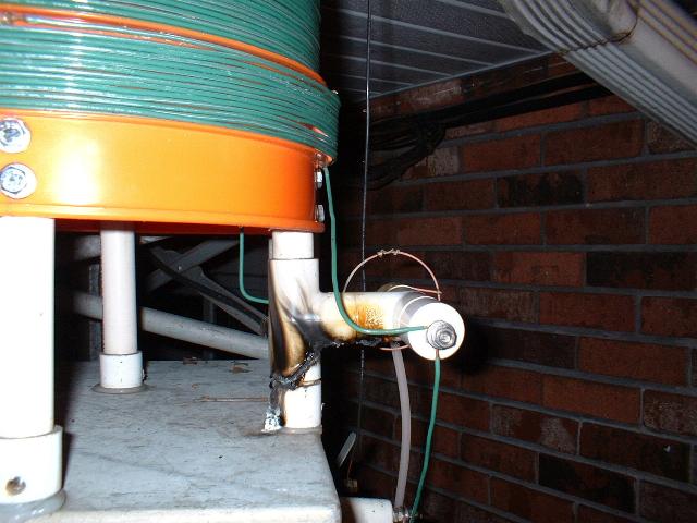
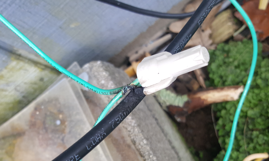
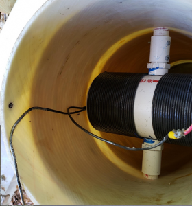
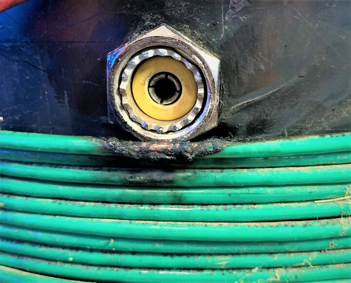
John, N2EIK, reported on the afternoon of October 6, 2019 that he has “
Been
down for a few nights. xmit & rcv went right down the pooper. What
the heck? Today I finally had time to look. There was a poorly dressed
coax that fell on top of the center conductor feed to the variometer. It
arced through the coax insulation and shorted the 630m feed to ground.
On the up-side, no damage was done to amps, etc. The green wire is the
main feed to the antenna, the coax was for a scanner antenna. There is a
wire nut(s) due to the switching arrangement in the feed. I can shunt
out(bypass)the variometer so I can still use the inverted L on 80 &
160.“
courtesy N2EIK
courtesy N2EIK
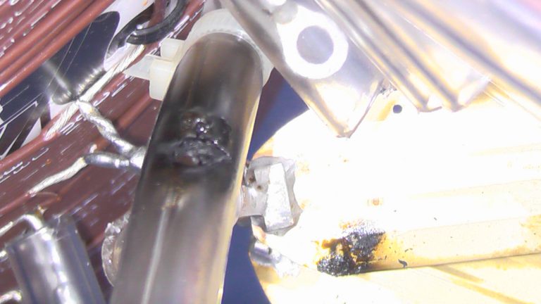
Eric, NO3M, submitted the following
image of what can happen when using an underrated relay to switch the
taps on an impedance transformer for his 2200 meter system. He
added that “
the
worst part was when xyl called me in the middle of testing, locked up
the remote access to station and couldn’t shut it down…. went 2 minutes
arcing…” Good times…
courtesy NO3M
ADDITION 12/23/19:
Eric had a second submission just days before Christmas as a panel on
the wooden helix house ignited between the output insulator and the
vacuum relay. While early reports are sketchy and require more
analysis, he reported in darkness that “
something in the wood siding
is igniting due to the intense RF field or something… I found no
failure in the insulator or the relay…“
courtesy NO3M
courtesy NO3M
Ward, K7PO, offered the following before and after images and explanation:
“
This was the current transformer on the Delrin feedthru to the antenna.
I think it was #77 or #78 ferrite. All was good on 630 and 2200 meters,
but when I did some 8 khz work things went wrong. At 8 khz the core got
hot enough to start the Delrin on fire…“
courtesy K7PO
courtesy K7PO
Keith, K0KE, submitted the following images, noting that he was in the middle
of a QSO with W7IUV when “…
the
big 2.5 mH coil arced to ground via a mounting tab that was attached to
the cabinet which was grounded. It was on the hot antenna
side of the coil running 75 w. I cleaned the coil and
remounted it on ceramic standoffs with no further problems last nite.“
courtesy K0KE
courtesy K0KE
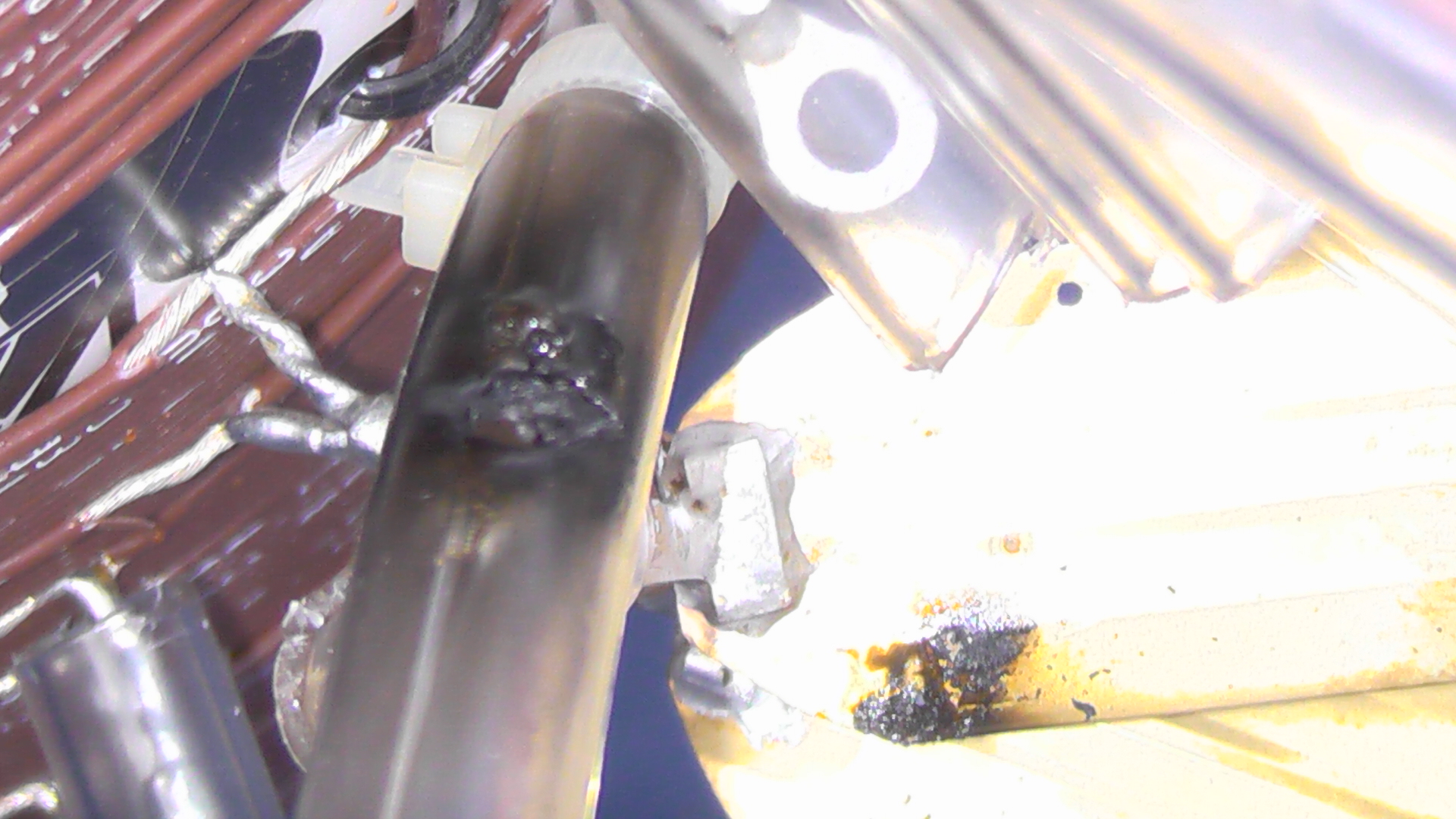
David, N1DAY, burned up an automotive relay. He explains:
“…I hate to go outside in the winter
to adjust my antenna settings, so everything is automated with 40A SPDT
automotive relays which have worked superbly at remote transformer
tapping and switching between 476 kHz and 136 kHz. So, I got the
idea to put another relay above the induction coil to allow switching of
the entire coil out of circuit to allow my LF/MF antenna to be used as
an HF antenna as well (the LF/MF Marconi’s work great on HF)…when the
aforementioned relay arced and burned from the high voltage (only about 7
kV – no big deal – hi hi), my amplifier immediately went bonkers, and
the oscilloscope generated only what I can describe as an unmedicated
schizophrenic waveform. Upon venturing outside to the antenna, I
could immediately tell that something was amiss from the acrid fumes I
detected. I was quite surprised, upon inspection of the antenna
elements, to find that such a small device as an automotive relay could
generate such a putrid smell that did not dissipate in the rain.
The relay has since been removed and will be replaced with a Tohtsu coax
relay rated for the appropriate voltage…”
courtesy N1DAY
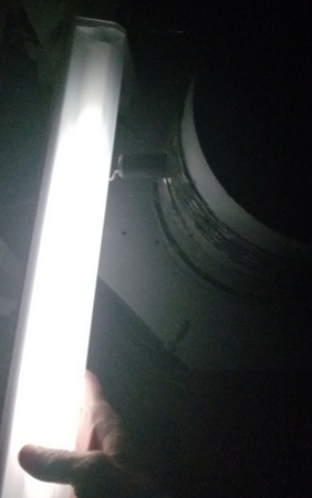
“I also attached a picture of a
florescent lamp next to my induction coil. I just had to see if
that actually worked, but do not recommend the practice as it resulted
in a charge on my person that was quite vigorously dissipated when I
touched the metal door frame of my house after conclusion of the
experiment.” That is an arc between the coil and the tube.
courtesy N1DAY
Frank, AA5IT, recently added a new amplifier to his system and reported the following fun:
“
I was using my amplifier tonight
and it was doing well. I made about 5 transmissions on WSPR and the
results were very good. All of a sudden on the 6th transmission I heard
the sound of arcing noise in my stereo speakers. I looked at the
SWR and if was about 25:1 so I stopped the transmission. I looked and
looked but didn’t see anything wrong. I took the amp out of line
and transmitted with just the transverter. Same trouble. Went out to the
loading coil and discovered smoke rising from the variometer. The coil
actually hits the side of the coil if I decouple it at 90 degrees. Where
it was touching the PVC looked like it caught on fire.“
Ken, K8HTL, showed what happens when gaps between high voltage windings and ground connections are not wide enough.
Not a lot of details on this one:
N1SV reported that on Friday, December 11, 2020 just after sunset and
receiving a WSPR report from LA2XPA, things stopped working.
Further investigation shows an arc occurred between the hot wire and
three to four of the moving coil windings. Potential difference is
potential difference and the following result occurred:
courtesy N1SV
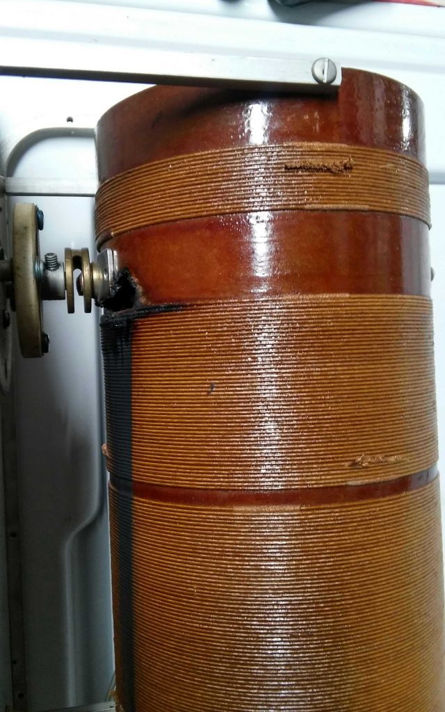
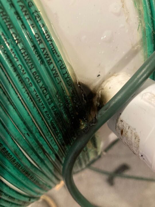
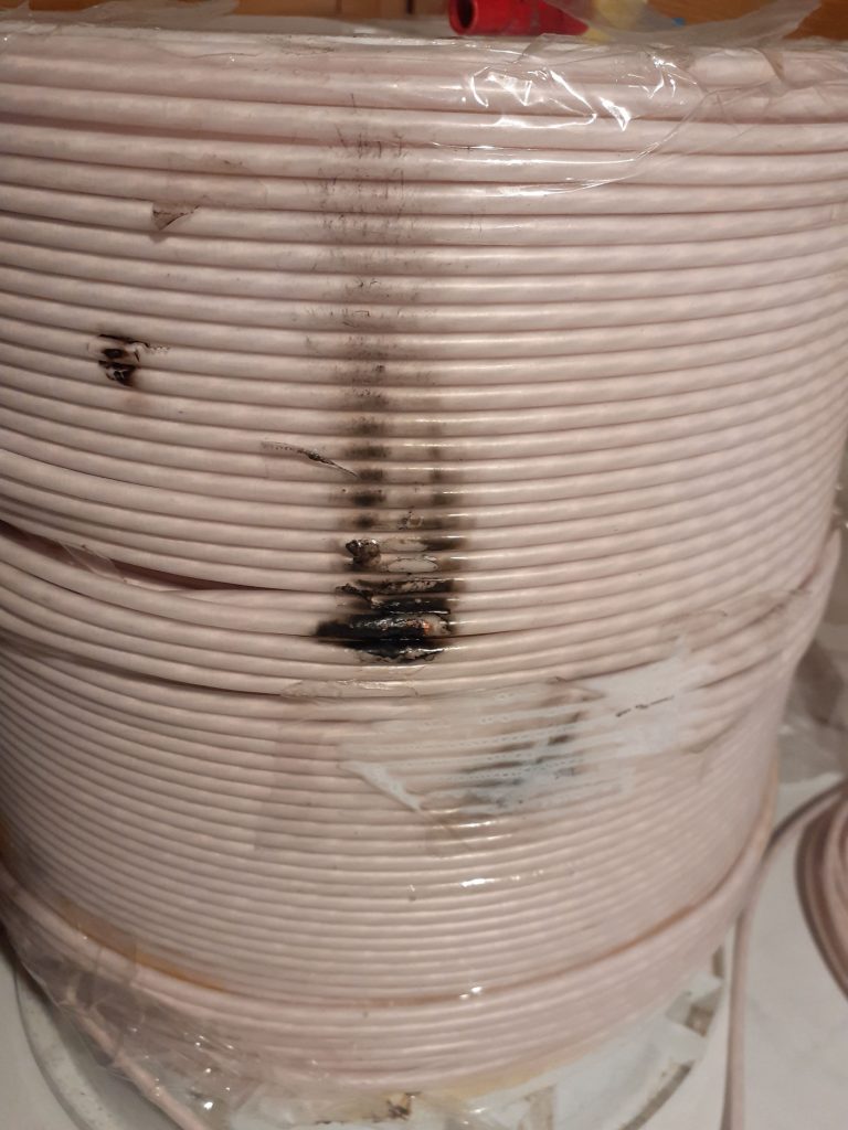
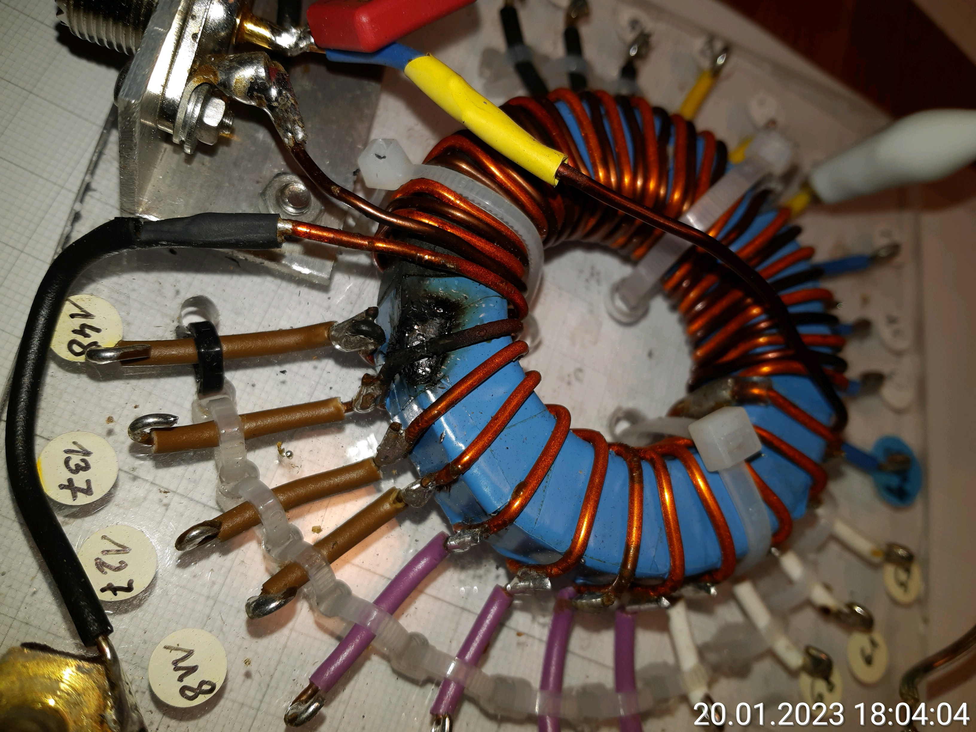
Markus, DF6NM, reported a 2200 meter coil fire. He noted that “
The
damage affected only some of the outer turns, so it could easily be
fixed by scraping off loose carbon, and generous application of Tesa
tape. The culprit was (of course) my own sloppiness: I hadn’t properly
straightened the wire going horizontally from the top of the coil to the
antenna uplead, such that it dangled loosely down the side of the coil
until it flashed over. ” By the time I posted this entry, he
was back on the air and didn’t waste any time with the repair. The
before and after images follow:
courtesy DF6NM
courtesy DF6NM
(larger image)
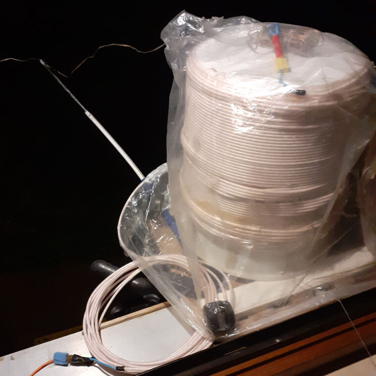
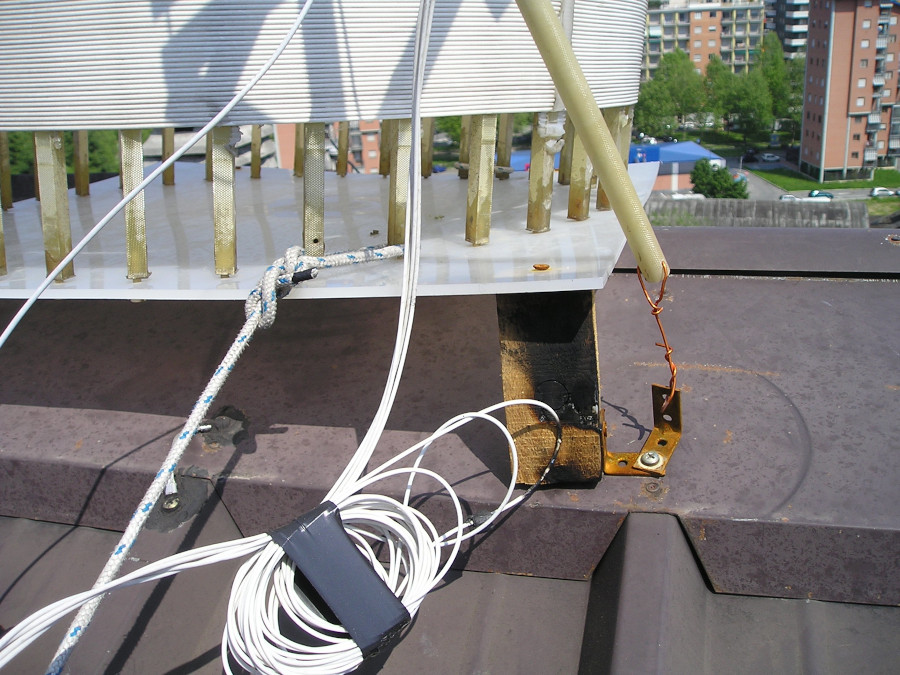
He noted in a subsequent email that “
This
may give you an impression of what the coil looks like. It is made from
Decca Litz wire, using a stacked multilayer winding in segments of 3×8
turns. The inductance is 5 mH, and the voltage 17 kV (rms) at 4 A. The
plastic stick is supposed to hold the upward wire away from the rim of
the roof. The resonance is adjusted by pulling on the thin yarn near the
bottom right, which rotates a 10 x 10 cm^2 ferrite slab inside the
bucket.
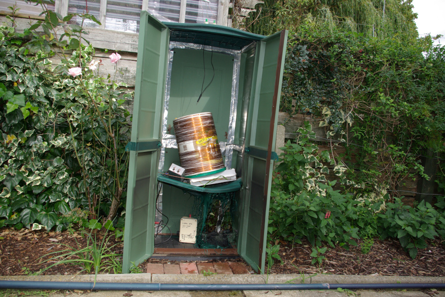
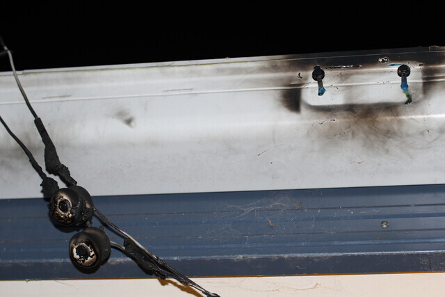
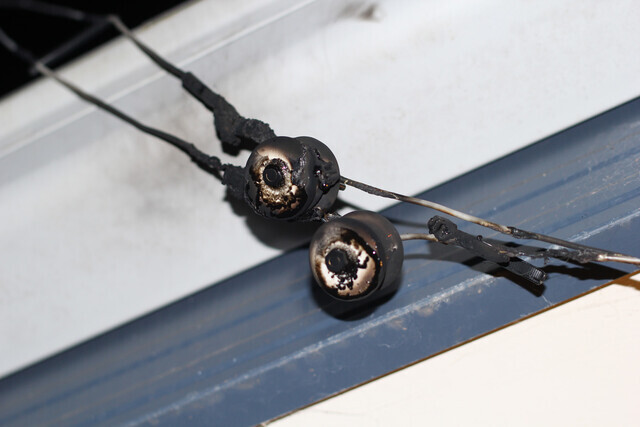
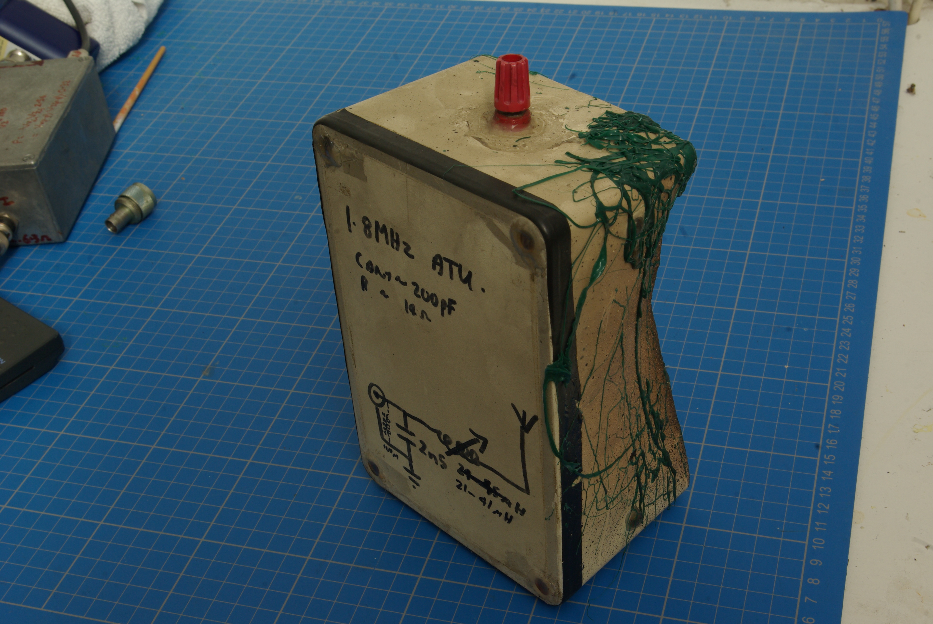
Andy, G4JNT shares details of something that happened to him some years back.
"At one point I decided to have an ATU cabin in the garden, at the base of my Tee antenna for LF. I bought a plastic garden shed / cabinet that clipped together, but noticed it had gaps that needed to be sealed which I did aluminium tape , the stuff designed for sealing air-con ducting and the like. What I hadn't appreciated is that this stuff was thin aluminium on a plastic backing, so overlapping joints were not connected - even worse, there was a small air gap at each crossover.
I installed the 137kHz loading coil and one morning fired up the 700 Watt switch mode Tx sending a beacon signal. After perhaps an hour I smelt burning plastic, but assumed someone just had bonfire somewhere burning rubbish. Another hour later it was worse so I went out to check, and found this. It had clearly been sparking at the overlaps and ignited the slow burning polycarbonate at the base. It would have continued slow burning for a long time if I hadn't spotted it in time, being fed by melted dripping plastic dropping down.
Fortunately the 137kHz loading coil survived, but the top band ATU in the white box that had just been sitting there in the shed had to be rebuilt."
courtesy G4JNT
(larger image)

courtesy G4JNT
(larger image)
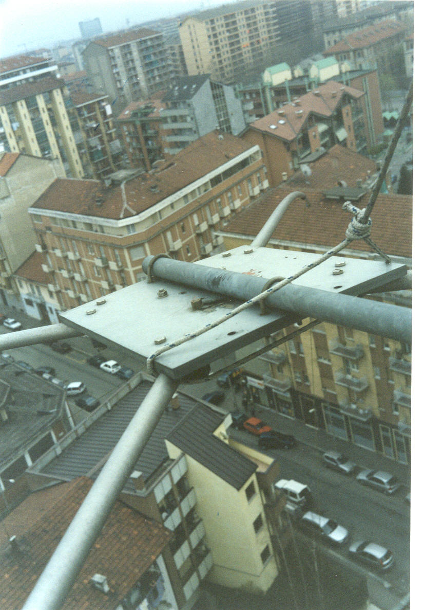
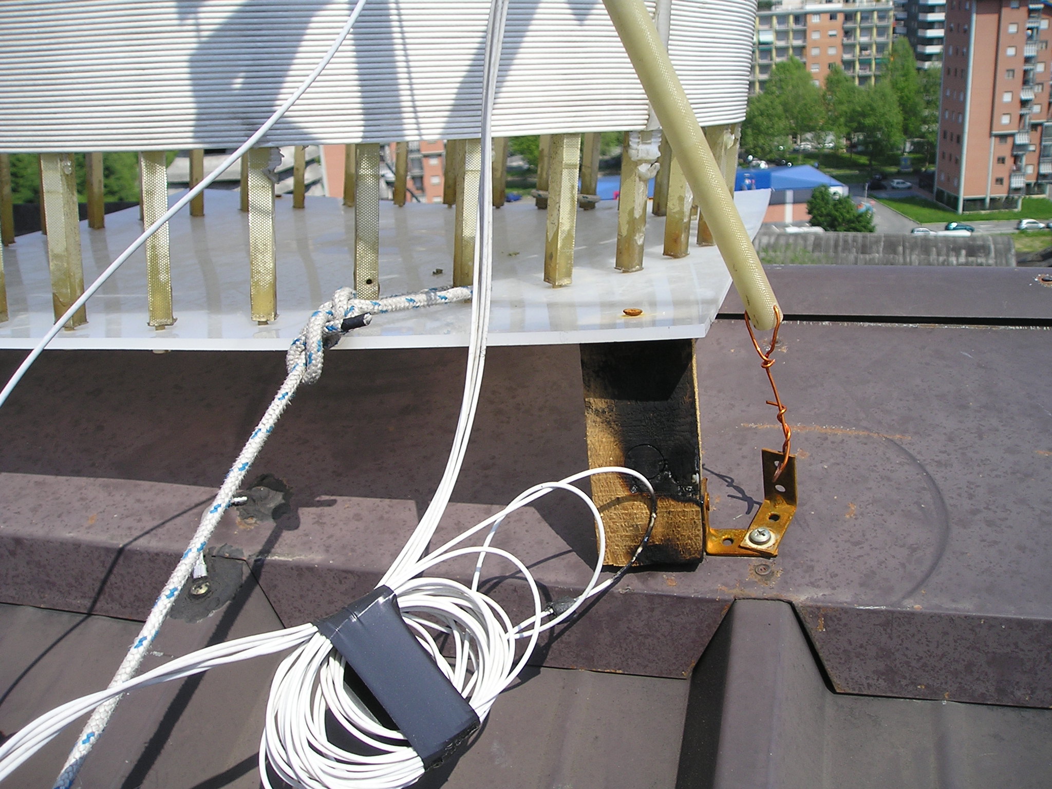
Marco, IK1HSS shares photos from several past experinces on 2200m:
"This was my very first antenna for 2200m. It was an inverted piramyd hang on the side of the main mast.
The top PE plate (abt 2 cm thick) was providing the insulation of the antenna from the supporting pipe.
All fine until a bird left a souvenir between the pipe end one of bolts."
courtesy IK1HSS
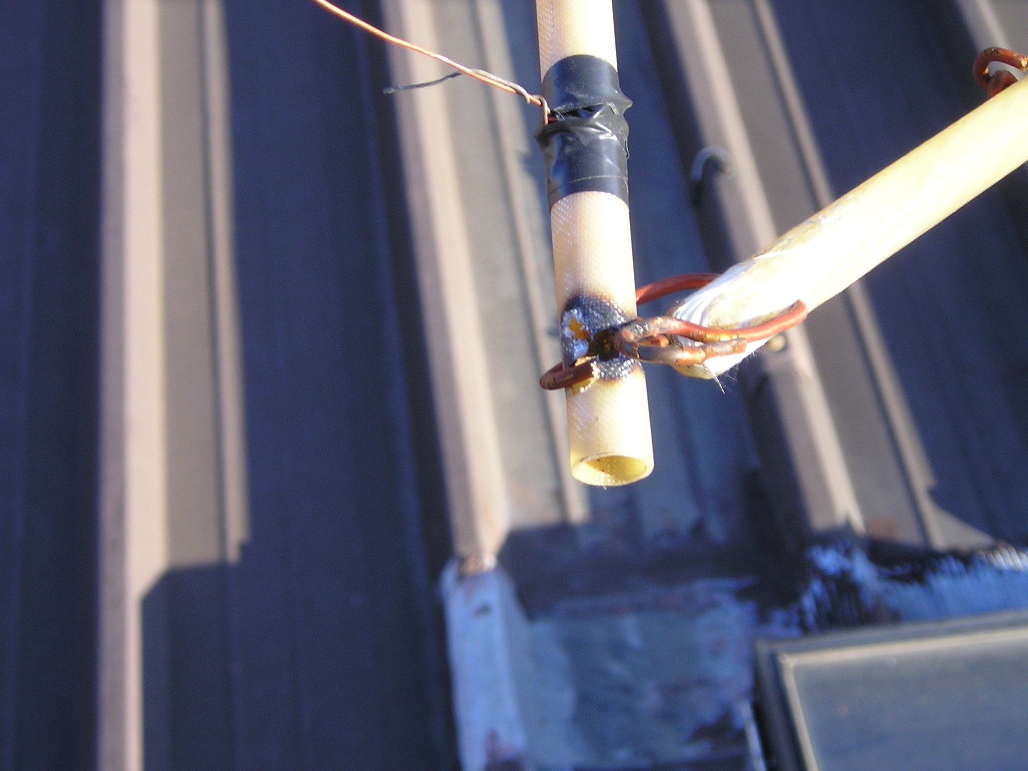
"The following antenna was a traditional T antenna stretched between 2 masts. After some time was not so stretched and the antenna wire went close to the base of the coil."
courtesy IK1HSS
(larger image)
"Corona at the end of the top hat. Better to avoid metals, even with insulation, close to the high voltage antenna ends."

courtesy IK1HSS
(larger image)
"Base insulator keeping the low end of the vertical wire away from the roof."
courtesy IK1HSS
(larger image)
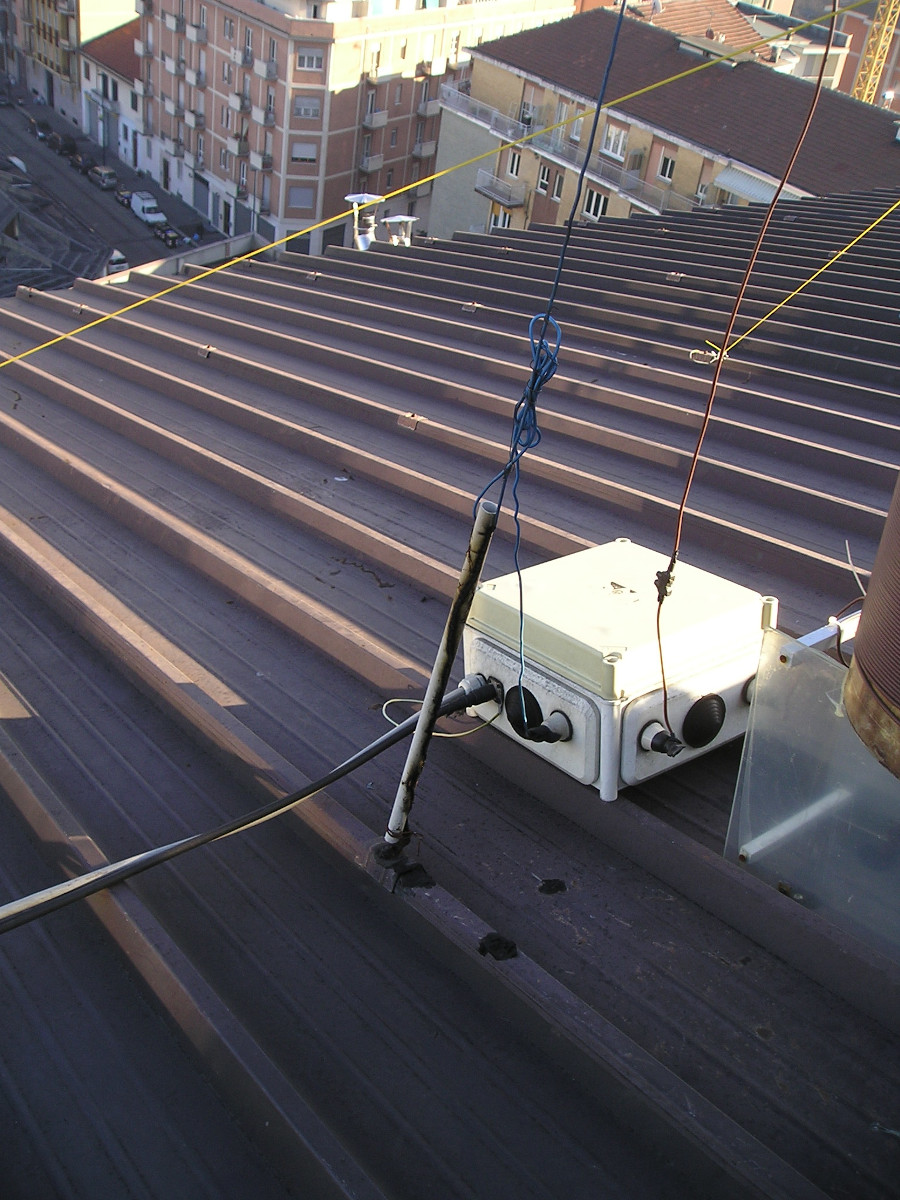
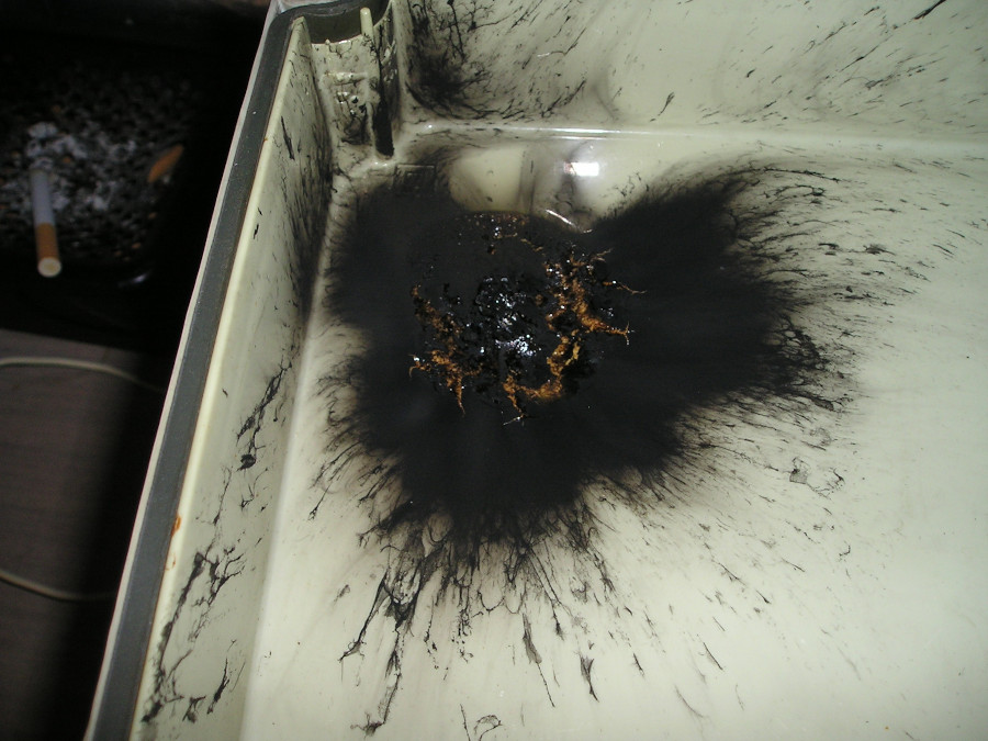
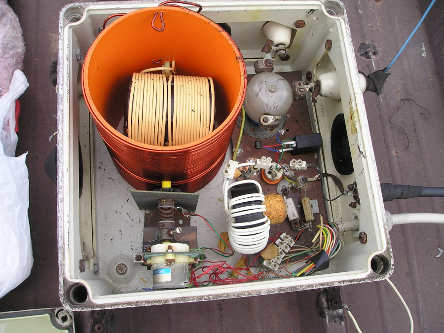
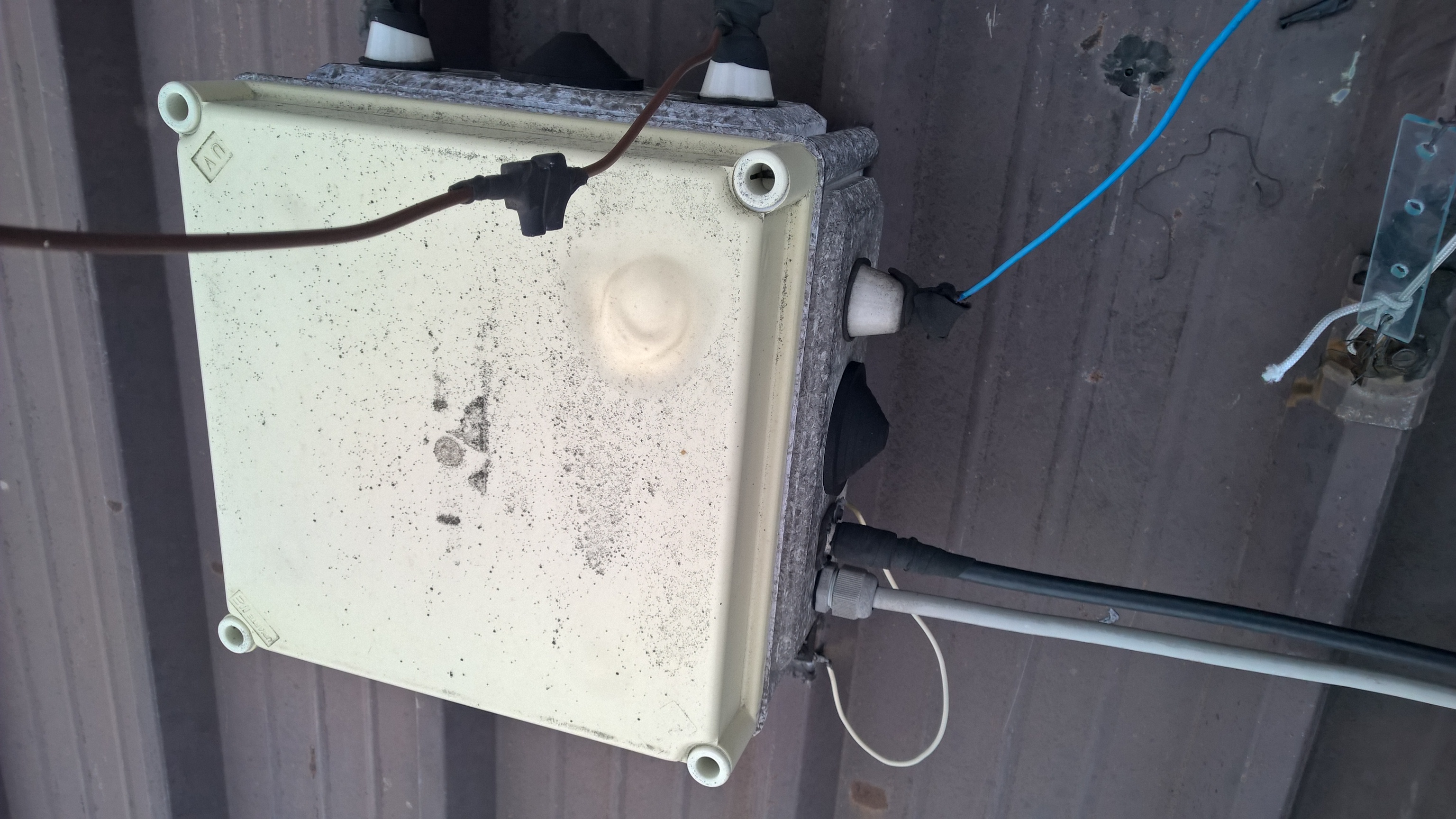
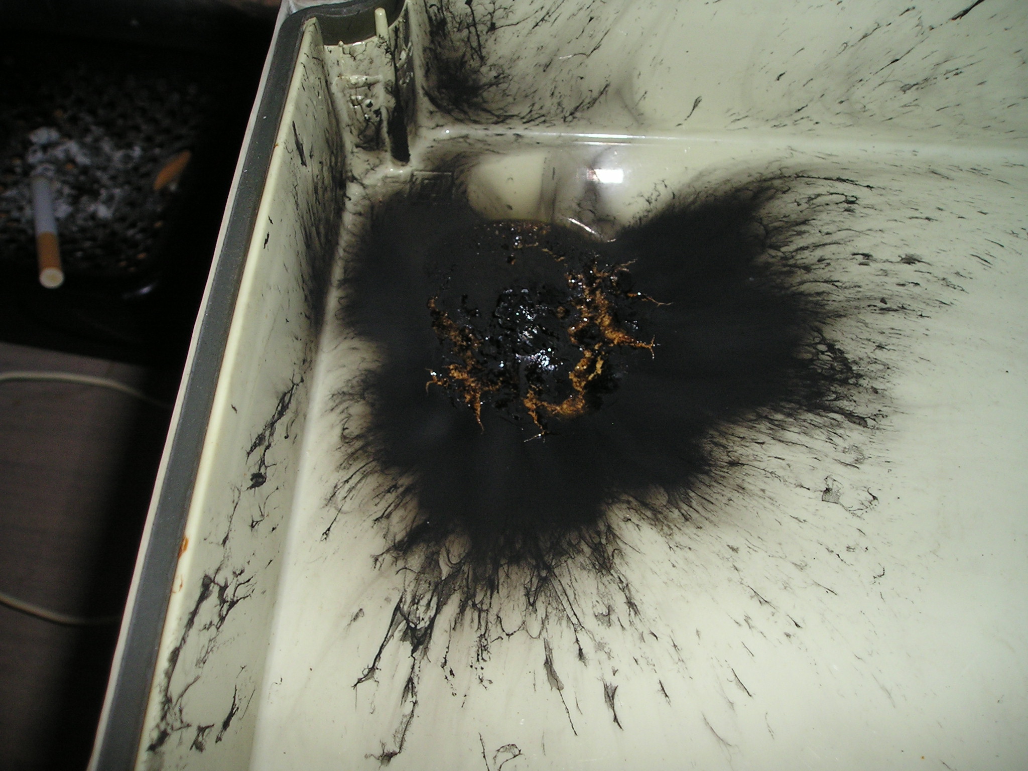
"When I tested on the antenna a new PA (600W) I noticed that something was going wrong. A visit on the roof at the switching / tuning unit reavaled that something was really wrong!
I suppose an arching between the vacuum ralay switching the LF coil and the cover of the glass fiber box. The box was plenty of carbon black: the compenents inside were dirty but healty. After careful cleaning of the components and a new box all was fine.
The PA is still sitting under my bed waiting for a better solution."
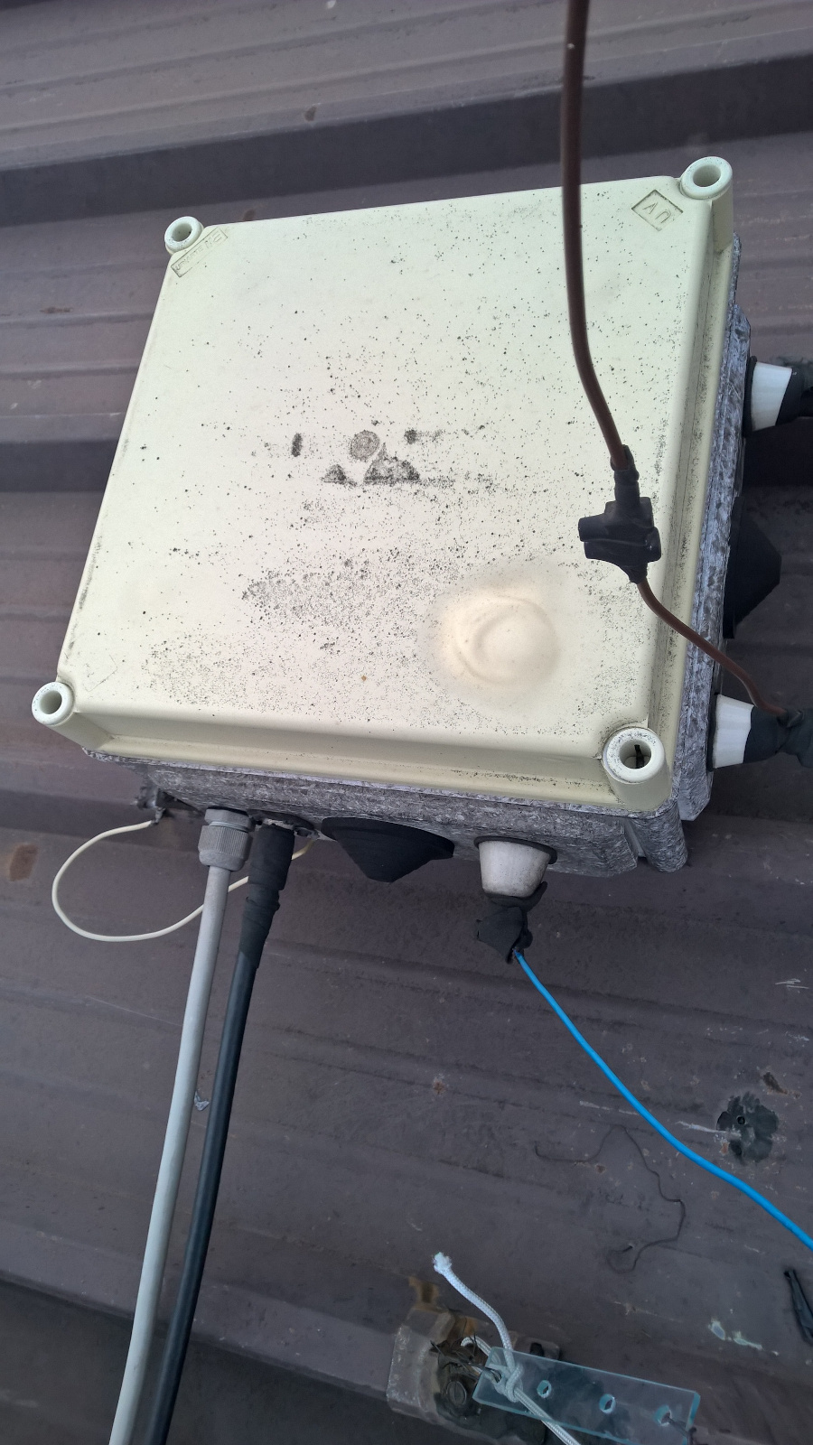
courtesy IK1HSS
(larger image)
courtesy IK1HSS
(larger image)
courtesy IK1HSS
(larger image)
"Back in the past when I used a transverter as rig with a push pull amplifier. An exploded elcap and well cooked RCA jack and some ehm damaged power FET."
courtesy IK1HSS
(larger image)

courtesy IK1HSS
(larger image)
Dick, W7WKR, submitted the following
story of RF-induced fire from back in the 1970’s. While not
specifically MF or LF, it shows what can happen with high-power RF when
things go very badly:
“My story goes back to late 1979
when I was living North of San Francisco and operating under an
N6-additional-station (my w7wkr was still in effect) license.
I was working DX on 80-meters using a
shunt-fed top loaded Rohn-25 tower. I noticed some weird behavior by my
SB-220 amplifier. I looked out my shack window to see a large grass fire
expanding around the tower base and knew _something_ was seriously
wrong !
A fast trip to the tower accompanied by
lots of stomping on burning grasses controlled the fire. The area
burning was an expanding circle about 10-feet in diameter and could have
easily grown to 1000’s of acres in the dry grasses. I hosed the entire
area down once I suppressed the outer perimeter flames’
I dodged a serious bullet on this one!
The source was a blown-up tuning unit. I beefed-up the tuner components
and never had tuner failures again.”
Added 06 February 2022:
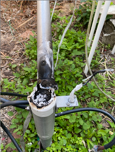
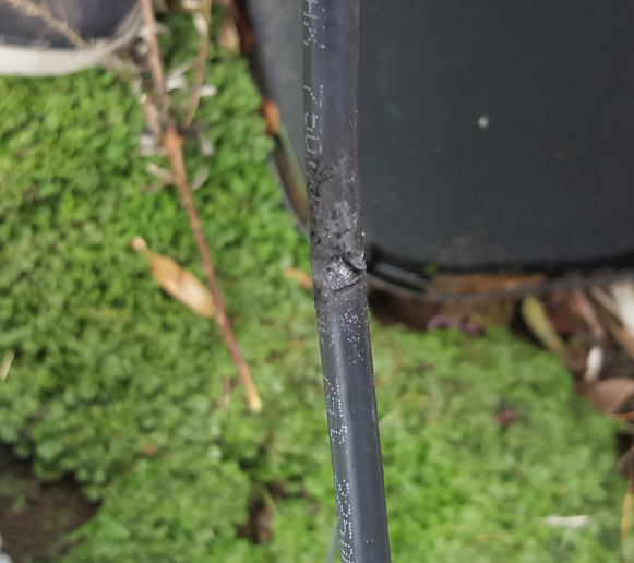
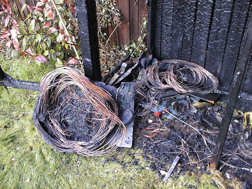
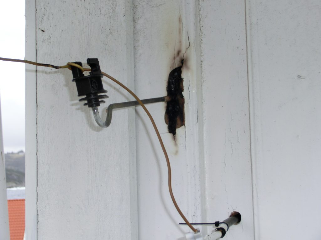
Peter, VK2AN submitted these photos and explains
"I had the feed (vertical radiator)
to the antenna on a Nylon block bolted to the gutter. It caught fire and completely
melted off the gutter and destroyed the deck chair underneath. "
courtesy VK2AN
courtesy VK2AN
Added 14 February 2022:
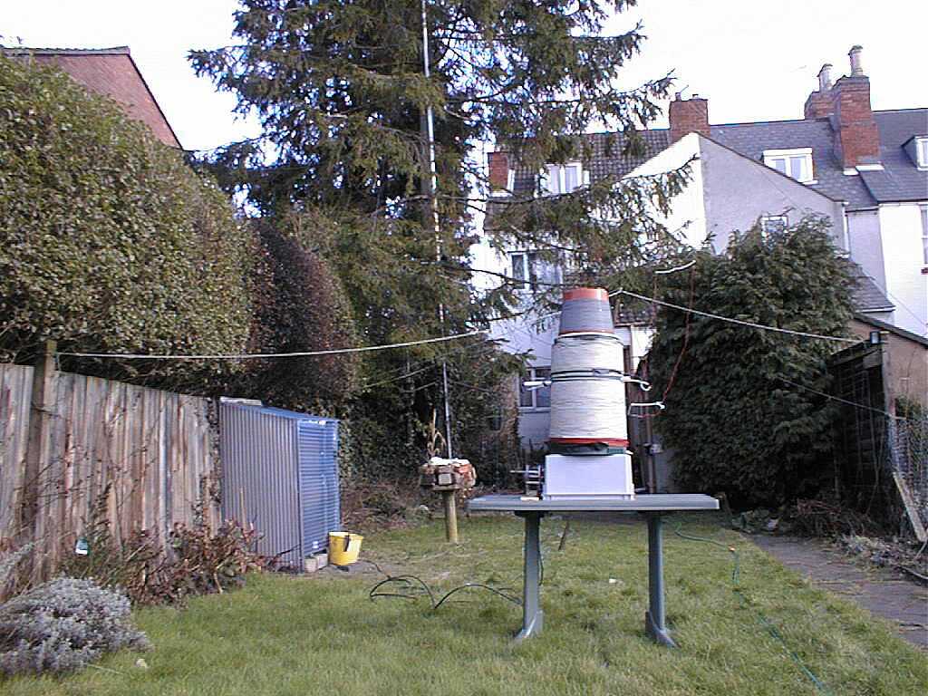
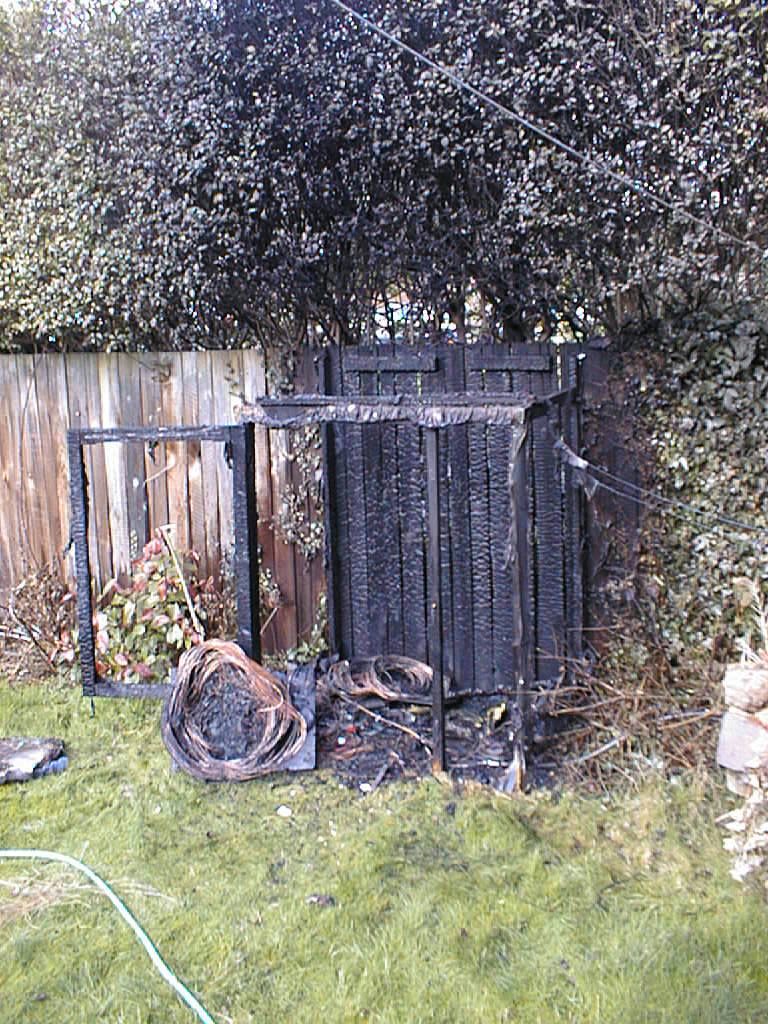
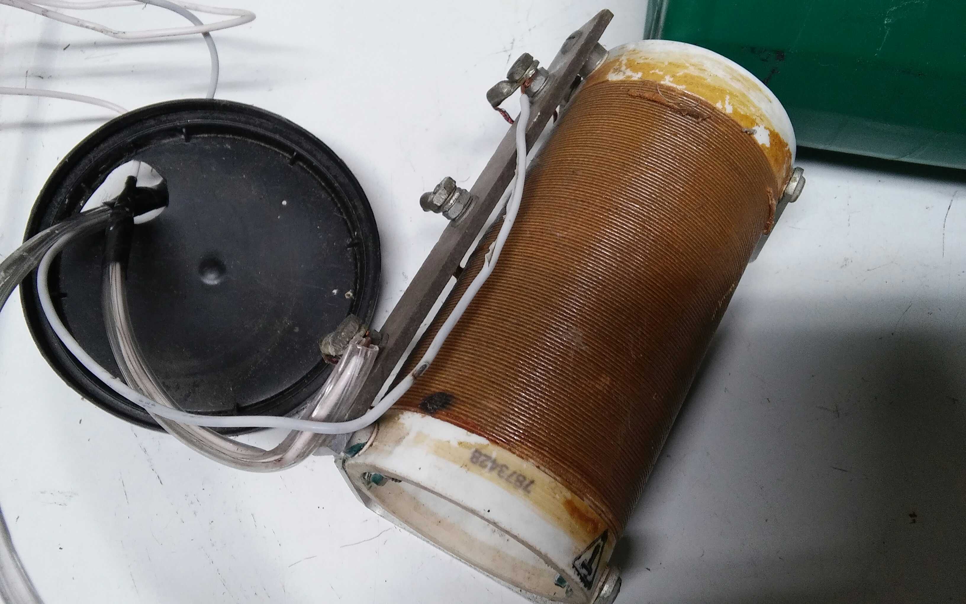
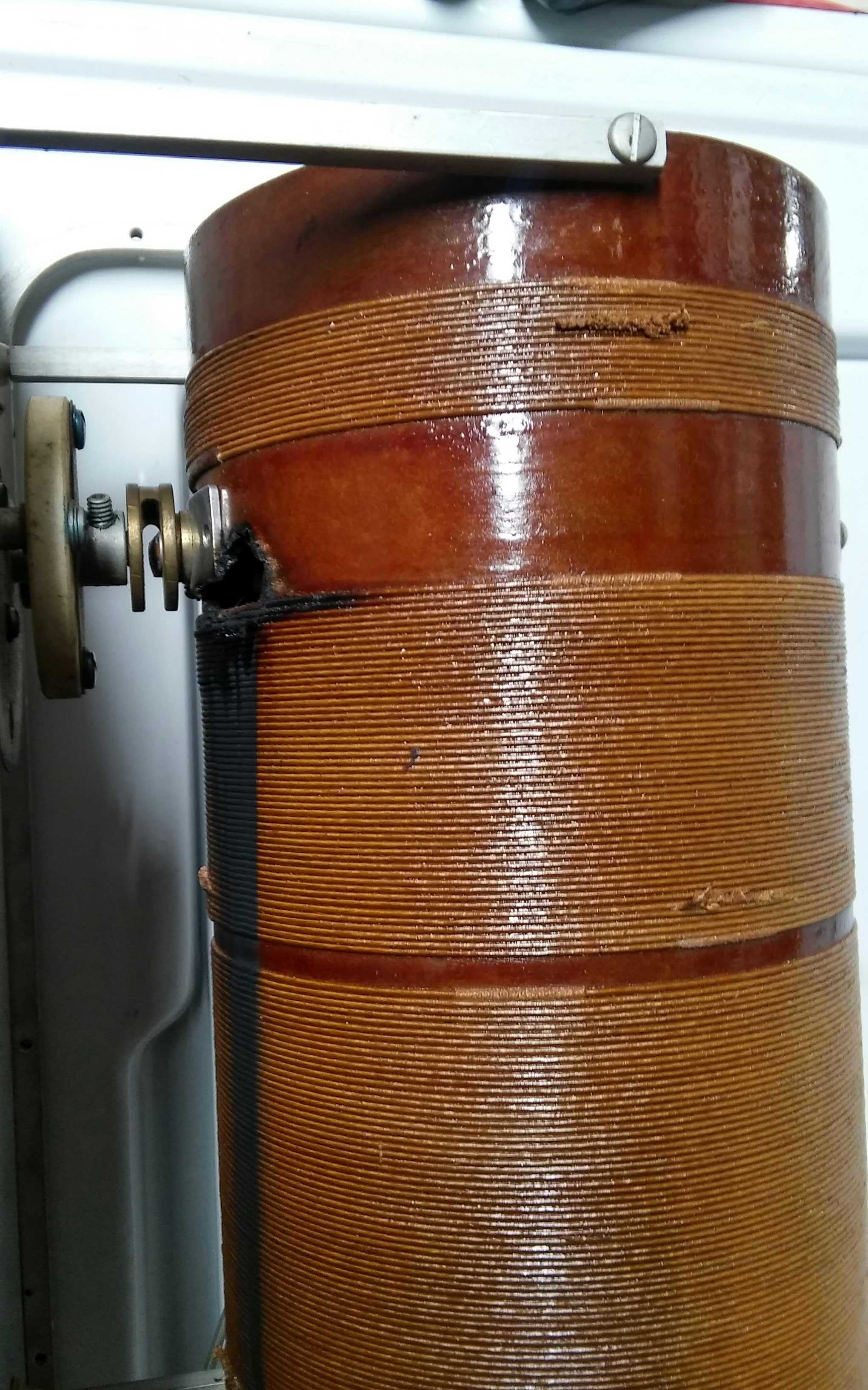
Dave, G3YXM had an incident with his LF antenna tuning unit:
"Back in winter 2000/2001 I had just completed "project 2k", a 2kW output class D transmitter for 136kHz. My antenna at the time was a 160m doublet configured as a "T" antenna and tuned with a large loading coil wound on a plastic drum. The tuning system had been installed in a small hut I had built next to the garden fence.
One day when testing the system my daughter, who was about 15 at the time, came into the shack and asked me why the garden was full of smoke. On rushing outside I saw that my lovely tuning hut was well ablaze and the flames were engulfing the hedge. Whilst I set about extinguishing the fire with the garden hose the Fire Brigade turned up and sprayed some water about too. They claimed never to have attended an amateur radio fire before.
I guess my liberal use of styrofoam as insulation between the parts in the tuning system was a bad idea? I now use old plates from the kitchen, they don't burn!
The shed was rebuilt soon afterwards."
courtesy G3YXM
courtesy G3YXM
courtesy G3YXM
18 December 2023:
Roland, OE9RMV reports "I am active on LF since Feb. 2022 and made some experiences regarding LF
high voltage breakdowns. Luckily there was no severe issue yet. Neither humans or animals nor
valuable material. And I try my best to keep it like that. I learned how to improve critical
components and avoid transmitting higher power during rain."
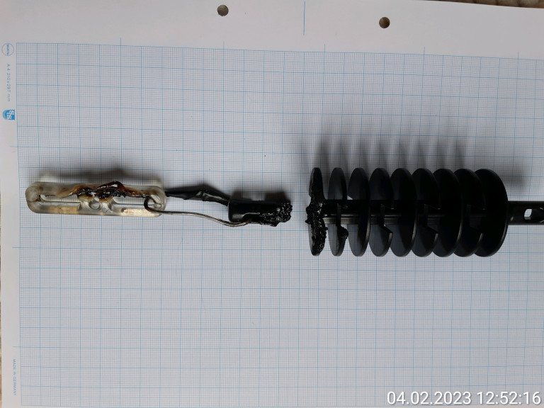
"Pic.1: Molten insulator during rainy weather. My T-Antenna had such an insulator-
configuration at both ends of the 3-wire flat top capacity. I was using 2 combined 360W class-D
PA's -> Peak voltage around 22kV.
Suddenly the antenna passed my window and fell on the grass.
I hit the main switch and immediatly went outside watching for potentilal fire.
The black insulator consists of PA (Polyamide) +PC (Polycarbonate). The transparent material is
PC only. Not perfect materials for our purpose. Looks like that there was sliding discharge on
the transparent insulator.
My worst mistake was the conducting wire link in between and using a bulky insulator (high C).
I know that high-frequency high voltage insulators are made from ceramic material, have to
be slim (low capacity) and long shaped. Avoiding sharp edges of the electrodes is the rule.
A glossy coating on the ceramic prevents from contamination over time.
Plastic can melt but I need light weight components. After improvements the antenna is now
electrically stable still using theese materials. For sure those materials degrade under
environmental stress and partial discharge. Perhaps after some Years I will have to replace them."
courtesy OE9RMV
larger image
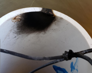
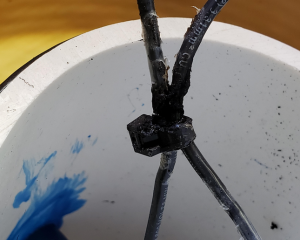
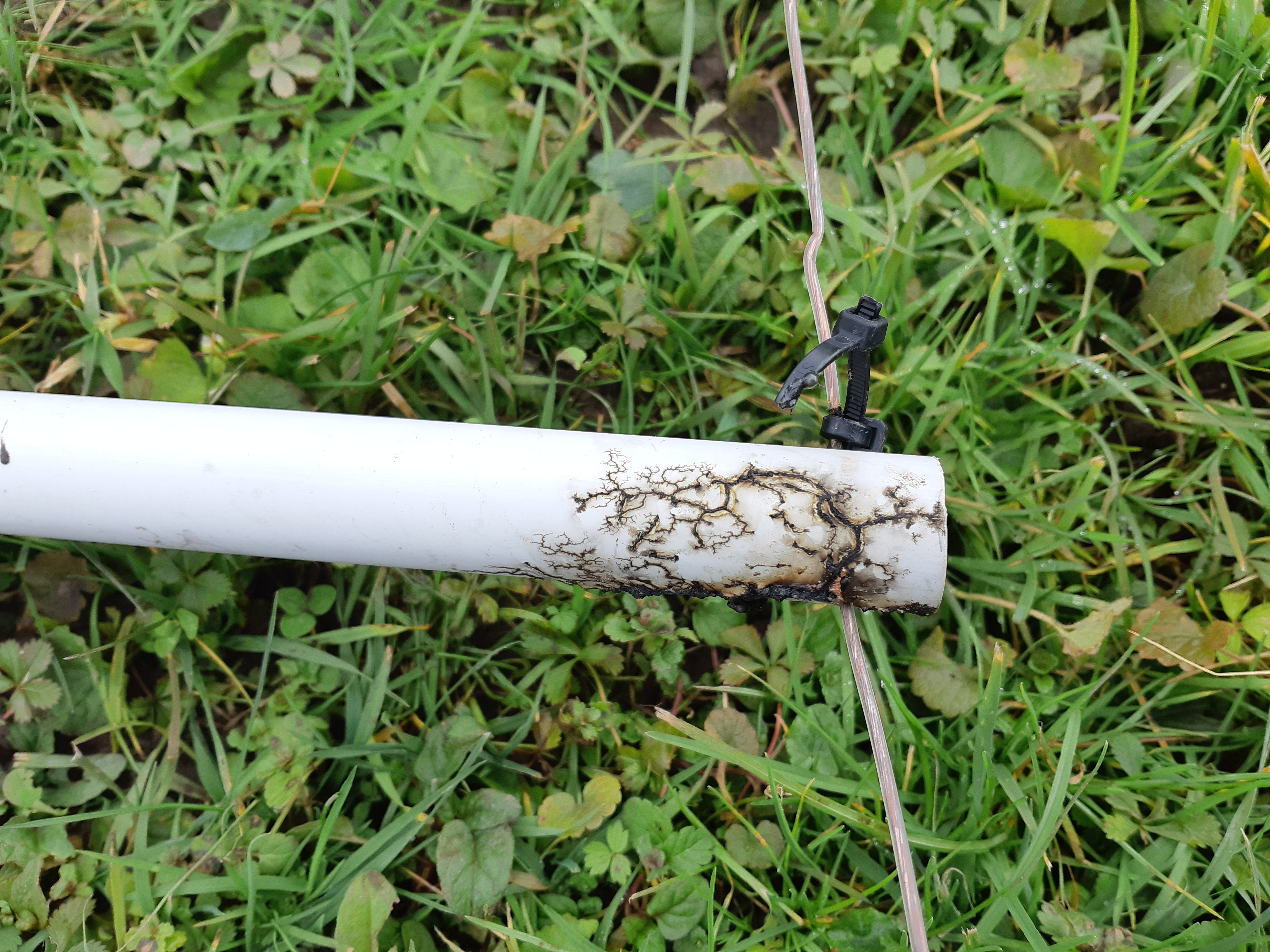
"Pic.2: Lichtenberg figures have eaten inside lossy PVC tube of my 3-wire flat top capacitance.
The coil has 4mH. The Peak voltage on the antenna is about 22kV."

courtesy OE9RMV
larger image
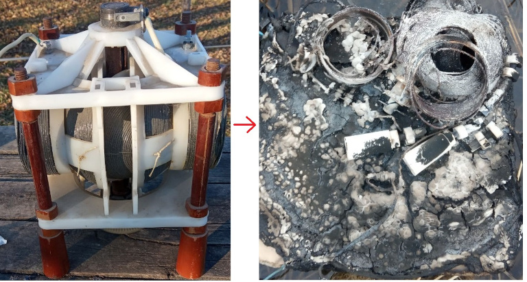
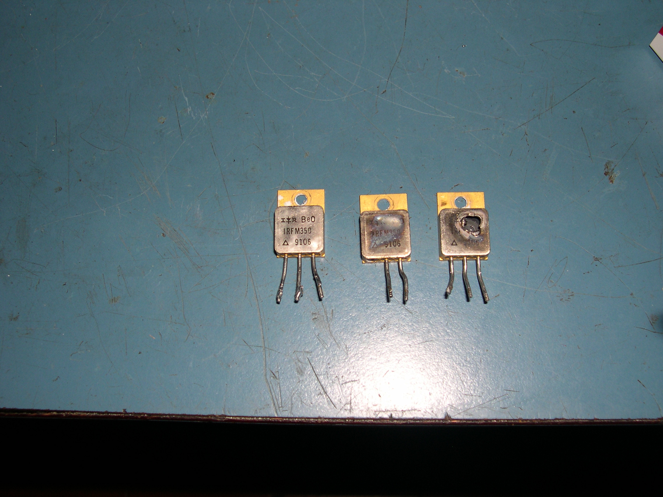
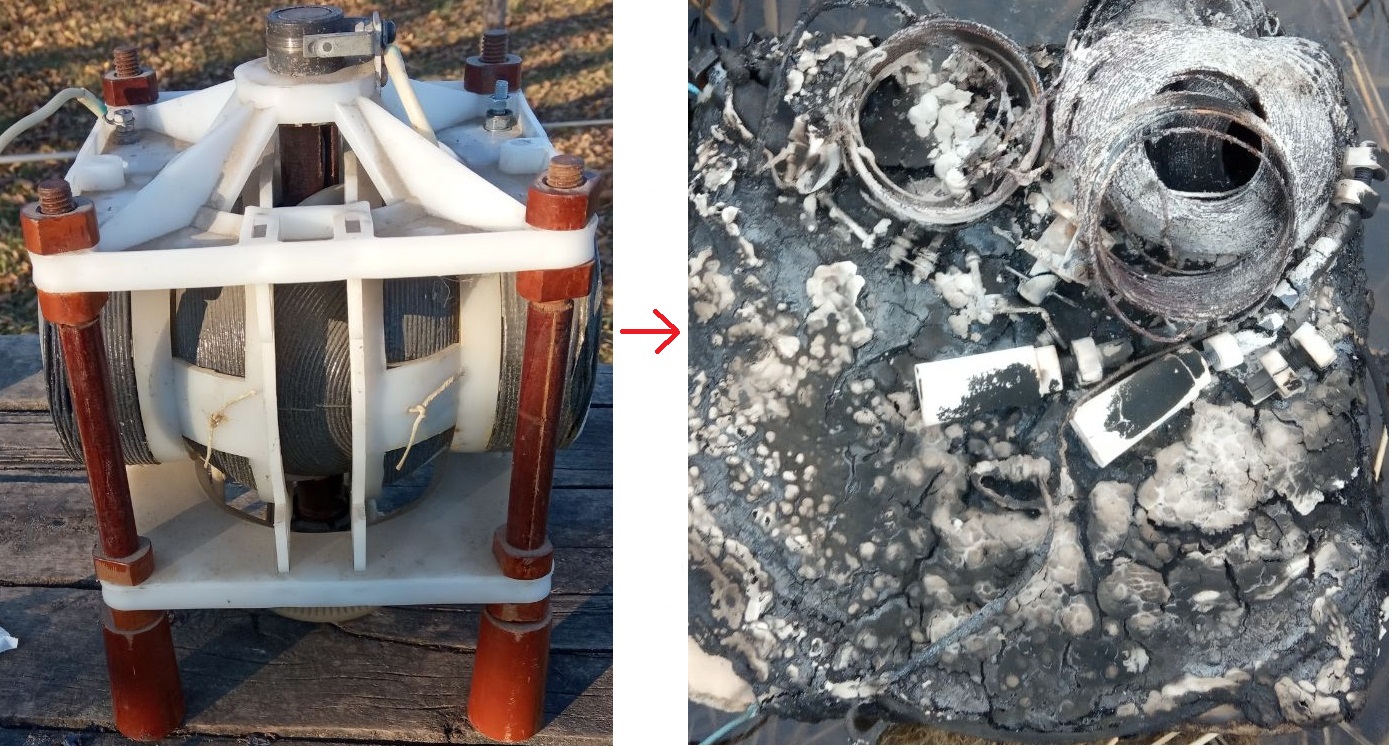
"Pic.3: Matching Transformer using FT240-77 core. Everything was stable using 360W, not
so for doubling this power."

courtesy OE9RMV
larger image
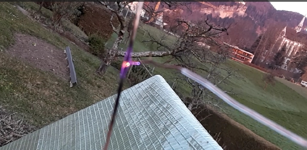
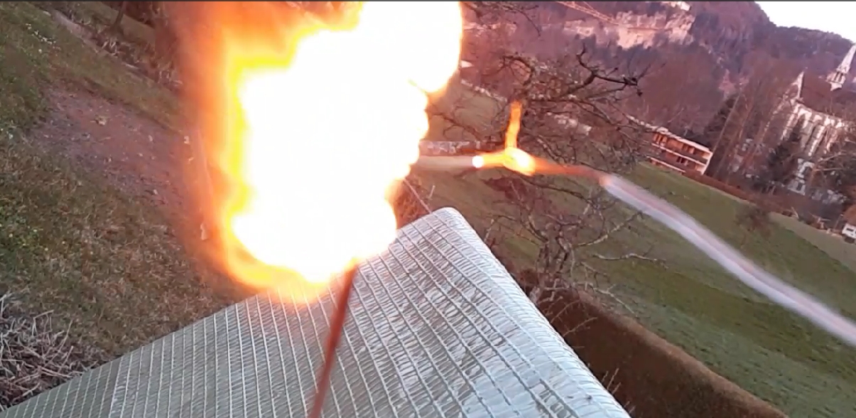
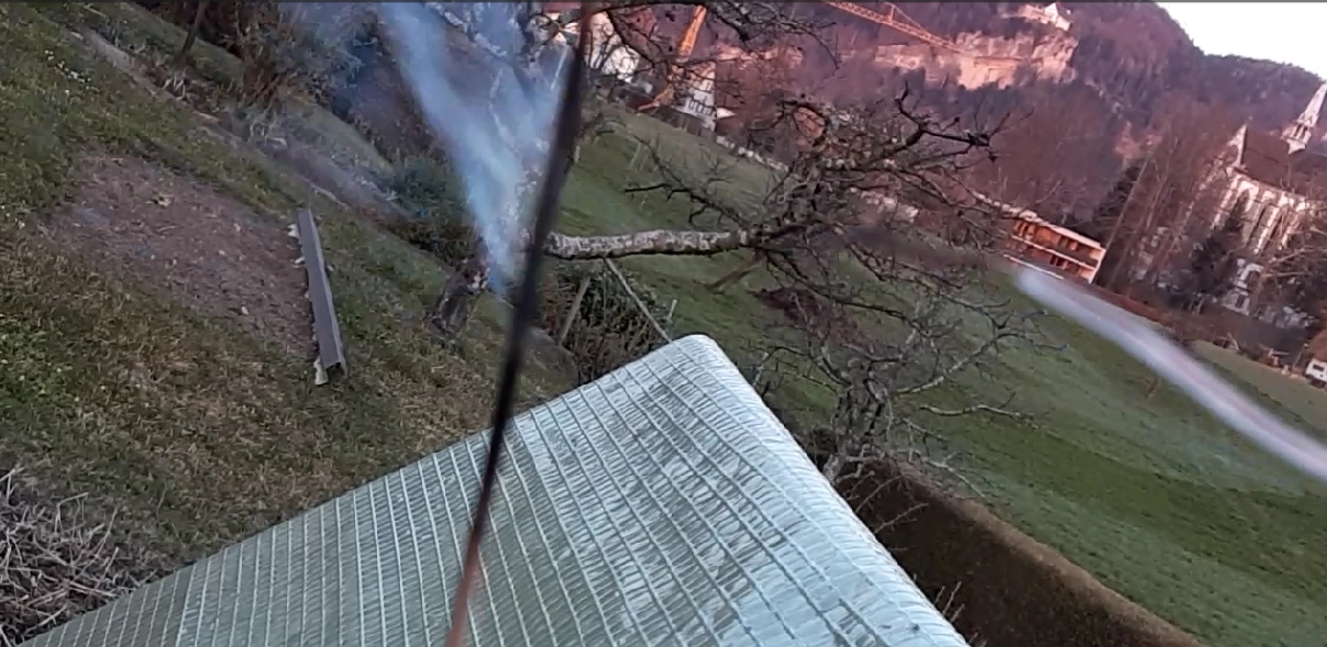
"3 pictures taken from a video I made. This was a test. I used 170W on my T-Antenna, 4mH coil:
carrying about 8kV peak.The wire going down was grounded and held by an insulating rod.
One can see that the PVC coating of the touched antenna wire immediately starts burning under
the plasma arc."

courtesy OE9RMV
larger image

courtesy OE9RMV
larger image

courtesy OE9RMV
larger image
03 March 2024:
Oleg, R7LP sends this before and after photo of his burned-out variometer.
courtesy R7LP
larger image
February 16, 2025:
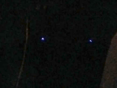
Markus, DF6NM reports:
"Last night the weather was cold and dry, so I turned on the transmitter and sent out a single FW-15 sequence on 137.51 kHz. Antenna current was a little above average at 4.3 A rms, or 19 kV rms on the antenna. Looking out of the window where the coil is placed, I noticed two little violet flames, dancing on the wire! Over the years, the polyethylene insulation has become very brittle, exposing the metal to the air. Looking more closely, I saw that the wire near the coil happened to have two kinks with sharp turns, producing those sizzling corona discharges. A short video is
here."
courtesy DF6NM
courtesty DF6NM
Have images of antennas, feed line, transmitters or related items catching fire or burning up
while operating below 500 kHz? Send it to me with a description! The more dramatic, the better.
Let’s be careful out there!
Please include your call sign in your message! Thank you.
