
N1BUG
Note: I hope to have illustrations, drawings, etc. to add to this eventually, as time allows!
Introduction
Types and Sizes of Cable
Yeah, but 75 ohms?
How do I use it?
Adjusting the Antenna
Trimming the Hardline
Connectors
Phasing Lines
Good Ideas from Others
Cable companies try to avoid splices wherever possible, and often discard cable ends. These range in length from a few feet to as much as 300 feet. These ends can often be obtained for free or very close to it. This is 75 ohm cable, but there is absolutely no reason why it cannot be used to good advantage in amateur installations. It has very low loss characteristics, very similar to that of 50 ohm hardline of equal size. I have personally used it to feed numerous VHF antennas, including both of my former 144 Mhz EME (moonbounce) arrays, and more recently on the Deepwoods Repeater Group 145.110 repeater: both critical applications! The method of cutting the cable to length is crude but works perfectly well. There is no reason not to do it with a return loss bridge, if one is available. Most hams don't have one, and it is my assumption that the reader does not.
Common sizes of this cable are 1/2" and 3/4". It is also made in other sizes: 3/8", 5/8", 1", and even 1.25"... but these are not common (at least not in Maine!).
At first glance, there appear to be two basic varieties of the stuff: those with the bare aluminum outer conductor exposed on the surface, and those with a (usually black) PVC jacket over the aluminum. Exept in rare cases, either one may be used with equal success. Since, in a properly matched antenna system, the RF current we are concerned about flows on the inside of the shield, minor weathering of the outside of the aluminum is of no concern, and will not increase the losses. I would not attempt to use the bare aluminum stuff on a repeater, however. Due to the full duplex nature of a repeater, any loose metal-to-metal connections will cause noise on receive, and it is very difficult to prevent the chaffing of the aluminum hardline against tower legs, etc. in the wind. It may be unwise for multi transmitter contest stations for the same reason.
That said, there is one factor to consider when choosing between the two varieties of cable. The bare aluminum stuff is very easy to kink if not handled carefully. The PVC jacket offers a measure of protection against kinking, and for this reason I prefer cable that has the jacket for many installations.
There are also at least three types of this cable as far as internal construction is concerned. Two of these use foam dielectric, the difference being in whether it is just plain foam or the "non-hydroscopic" flavor which will not absorb or propagate moisture. The non-hydroscopic foam type is to be preferred if you are not certain of your ability to seal out water at the connections! How to tell the difference? In the non-hydroscopic variety, the foam dielctric feels quite "hard", and generally has rather large "air cells" in the foam; it will also be glued to the center conductor and to the inside of the aluminum jacket. The regular foam type looks and feels more like dielectric in more familiar foam cable, such as RG-8/U foam, and usually is not glued to the center conductor and aluminum jacket. Losses with either of the foam varieties is about the same as for the corresponding size of 50 ohm hardline.
The third variety is known as "air cell" or "fused disc" cable. This stuff is mostly air dielctric, and has a thin layer of (usually clear or slightly opaque) poly around the center conductor, and another thin layer on the inside of the aluminum shield, with "discs" of the same material spaced 1 to 6 inches apart to hold the center conductor in place. Sometimes the center conductor is bare, and is only touched by the supporting discs. This variety has lower loss than either of the foam cables, and is great for long runs or loss-critical applications such as EME. But be careful: if water gets in, you will have big problems! Once water has intruded into the first cell at one end of the cable, changing barometric pressure will "suck" it from cell to cell, and soon the whole cable will be destroyed! Seal, seal, seal, seal the tower end of this cable: but drill a small air hole through the jacket and shield somewhere inside your shack or where water cannot get to it to minimize pressure differential between the cable and the outside atmosphere.
YEAH, SOUNDS OK, BUT 75 OHMS??!
Yep. With certain limitations, perhaps. There are several ways to use 75 ohm cable on a single band without increased SWR or losses. Mulitband use is another story, and will not be covered here. It is necessary to do things right, and it can take a little longer to install and "prune" the 75 ohm cables... but your efforts will be rewarded with excellent performance at very low cost. Now what could be better than that?
One common way to use 75 ohm cable in a 50 ohm system is to use quarter wave matching sections at each end in order to transform the impedance from 50 to 75 ohms. These can be homebrewed or purchased, but I have found this method to be undesirable for several reasons: cost; an extra potential water entry point; time consuming to build; etc.
Before going further I would like to clear up a little potential confusion here. I often see it stated that
if 75 ohm line is used in a 50 ohm system without any attempt at matching it the SWR will only be 1.4 to 1.5 anyway.
Well, that is true in a way... if the antenna is 50 ohms, the SWR between the antenna and the line will be about
1.5. However, from transmission line theory we know that a quarter wave line acts as an impedance transformer if
the load is not the same impedance as the line. We also know that a half wave line repeats whatever impedance it
sees at its termination point, independent of the line impedance. What this means is that the SWR at the transmitter
end of the line can vary anywhere between 1:1 and 2:1 depending on line length. Assuming a 50 ohm antenna and 75
ohm line the limits are:
* Line is a multiple of a half wave - SWR 1:1
* Line is an odd multiple of a quarter wave - SWR 2:1
It can vary anywhere between these limts. So don't expect to always see a 1.5 SWR if you are using 75 ohm line
feeding an antenna which has been adjusted to 50 ohms.
The other method, and my favorite, involves cutting the line to a multiple of a half wavelength at the operating frequency. Recall from antenna and feedline theory that reguardless of the characteristic impedance of the line, the impedance the line is terminated in repeates every half wavelength along the line. Say what? This means that if the antenna is properly set up to provide a 50 ohm load at one end of the line, and the line is an exact mulitple of a half wavelenth that 50 ohms will also show up at the far end or the line!
One step at a time. First things first...
The first thing you must do is adjust the antenna so that it is 50 ohms. If you don't have 50 ohms at the antenna end, you will have trouble getting it at the rig end!
Proceed as follows: Get a good (read new) piece of high quality (not Rat Shack) RG-213 or RG-8 cable with solid dielectric. Cut it to exactly one electrical wavelength, by using the formula:
Length(ft) = 984/f(MHz) * Velocity Factor
The VF of RG-213 is 0.66, so for example let's pick 144.2 MHz as our operating frequency:
L = (984/144.2) * 0.66
L = 4.50 feet.
Install connectors. The final length, from tip of center pin to tip of center pin, should be the length calculated above. Connect one end of this cable to your antenna, and run the cable down the boom or away from the antenna connection point exactly the same as the final cable will be in the final installation! Attach an SWR meter to the other end of this cable, and then run a random length piece of cable from there to your transmitter. Now very carefully adjust the antenna for 1:1 SWR (or close to it). In practice, 1.2 or even 1.3 is close enough, but get it better if you can.
While tuning the antenna, do not stand in close proximity to the driven element while chekcing the SWR, as this may detune the antenna somewhat. The reason for the one wavelength piece of cable is to assure that what you are measuring is the actual impedance presented by the antenna, and please do not try to get by without it! Try to keep the antenna at least one wavelength away from ground (or point it straight up) and other conductive objects during this process.
Also, if you are to be putting up more than one antenna (as in a stacked array) it would be very wise to mount all antennas on the supporting frame before adjusting them as just described. Then adjust each antenna individually for lowest SWR. The reason for this is that mutual coupling between antennas will affect the SWR slightly.
Next we have to cut the hardline to a multiple of a half wavelength. Do NOT try to do this by relying on any published velocity factor for the cable you are using. The VF of CATV hardline is not held to close enough tolerances during manufacture for this to work. Believe me! I learned this the hard way! Cut and try is the only way to do this!
Now that the antenna has been adjusted, attach the hardline to it (See the section on connectors, below). NOTE: if you need a flexible piece of coax to go around a rotator or whatever, you can use 50 ohm or 75 ohm of whatever length is convenient, from the antenna feed point to the end of your hardline. My personal preference here is toward using 75 ohm coax, but it really shouldn't matter (much). Alternatively, you can run a random length of your 75 ohm CATV hardline along the boom and down to the rotator, then use a flexible piece of 75 ohm coax around the rotator, then continue on down from there with the rest of your CATV hardline. Although this adds one extra connection, it reduces losses a bit more and is an approach I highly recommend!
OK. So, run the hardline to your station, and cut it about one half wavelenth longer than you need to reach your gear. Stick a connector on it (and you may be able to to this in a temporary, unsoldered fashion if you are careful... see below). Attach your SWR bridge either directly to the connector on the hardline, or use your one wavelength piece of RG-213 between the bridge and hardline. Now check the SWR. If it is higher than what you had the antenna adjusted for, you will need to trim the hardline until it comes down.
The safest way to do this is to trim the hardline a little at a time until you get the same SWR you measured at the antenna earlier. I'd recommend a half inch at a time for 144 MHz, and less at higher frequencies. An inch or two at a time will work on 50 MHz.
However, if you believe your SWR bridge is accurate there are some shortcuts. I do this myself, but I don't recommend it to anyone who has not been through this process several times. If something goes wrong, it can ruin your whole day! If at some point in the process you measure an SWR of 2:1, you are about one quarter wavelength too long on the hardline. You could speed up operations by cutting off almost a quarter wavelength (taking the approximate VF of the line into account) all at once. For the foam cables, the VF is in the 75 to 80% range; for fused disc, it should be 83 to 93%. On the other hand, if when you first start trimming you notice the SWR was almost low enough (but not quite) and it goes slightly higher when you make that first little cut, then you are almost a half wavelength too long... and you could try cutting off almost a half wavelength in one whack. These shortcuts can save time, but remember they are not always safe (much depends on the accuracy of your SWR bridge). Warned you, I did!
Once you are satisfied with the SWR (or get it as low as it will go, and it should come down to at least what you had at the antenna), you are ready to permanently install a connector on the hardline. Then use a random length of 50 ohm coax to hook it to your transceiver or whatever. There is no reason why you should not connect the hardline directly to yor rig, if it is convenient to do so and the situation is such that your rig won't end up dangling in the air...
I have seen methods of installing modified UG-21 "N" connectors on this stuff... mostly in the EME newletters over the years. I have yet to try this myself.
I personally have no problem with using "UHF" PL-259 connectors (teflon / silver, please!) at frequencies below 400 MHz. These can be easily (?) installed on the 1/2" CATV cable:
If the cable has a PVC jacket, strip it off to a length of 2.5". Cut and remove 1.625" of the aluminum jacket. On fused disc cable, also remove all dielectric to a length of 1.625"; on foam cable, taper the foam dielectric from full diameter right next to where you cut the shield off down to about a quarter inch diameter at 1" from the end of the cable. This is easily done with a knife. NOTE: on some cables where the foam is glued to the shield, you may have to slit the shield lengthwise to peel it off the dielectric. Be careful with the center conductor. It's copper plated aluminum: don't flex it back and forth too many times, and don't scrape all the copper off. Make certain the aluminum shield is clean.
Slide the outher shell of the PL-259 over the end of the hardline. The body of the connector should slip right into place so that the back end of it butts up against the aluminum shield on the cable. If you are using foam cable and left some of the dielectric on, you may have to screw the connector over it. The center conductor should fit into the center pin nicely. The center pin can be soldered for a permanent installation. For a temporary connection, you should be able to put a very slight "S" bend or similar in the center conductor prior to pushing the connector on; this will cause the conductor to fit tightly into the connector center pin.
Screw the outer shell of the connector over the body. Now for the electrical connection to the shield. Take a 1.25" long piede of 1/2" ID aluminum tubing, and cut it in two lengthwise. Make certain the inner surface of it is clean. Place the two halves together around the connector body and the exposed hardline shield, butting one end up against the outer shell of the connector (which should be pushed as far forward toward the tip as it will go). Wrap several layers of vinyl tape tightly around this to hold it firmly in place. After the first layer or two of tape goes on, you should apply thin coats of RTV silicone or a similar sealant between layers of tape. Secure the whole thing by tightening two 1" stainless compression ("hose") clamps over the tape. One clamp should be over the rear of the connector body, the other over the hardline shield.
This method of attaching connectors looks terrible and works great. I've yet to have a failure in one of these, and some were up for almost 10 years. Beware that this is not, in itself, a waterproof connection! The secret to waterproofing is in the overall assembly, after the thing is attached to the antenna! Hint on taping over the whole assebly after connecting to the antenna driven element: If the driven element can be removed from the boom easily (CushCraft, for example), remove it temporarily... you'll be able to tape around the connector much more easily!
On 3/4" cable, I've used a PL-258 (female/female) adapter to good advantage. "Core" out the dielectric from the end of the cable to a depth of about 3/4". A CATV coring tool, made for the job is great; a Dremel tool or equivalent works well; but it can be done with a knife, screwdriver, or whatever if you have patience. Make sure there is no dielectric remaining on the center conductor or the inside of the shield. Push the PL-258 into the end of the cable. You will probably need to use a shim of aluminum sheet wrapped around the threads of the PL-258 to make it fit better. Wrap the outside with tape and secure with a stainless compression clamp, placed such that it will compress the shield onto the connector as it is tightened. Of course, you do end up with a female connector this way... that can actually be an advantage in some situations. If not, just use a male/male adaptor.
Note on connector losses and SWR: I would not be inclined to lose too much sleep worrying about these intallation methods and "extra" connectors based on my experience with them in the past. On the EME arrays I was concerned, but subsequent testing with return loss bridges etc. proved everything was working very well.
In recent years I have at times left the compression clamps off the assembly (only on 1/2" cable! It's needed on the 3/4" system!) in order to make it look better. This has been successful in all but one case; and that failure was caused by slight and repeated flexing of the cable end, along with a minute hole that allowed water entry.
I have successfully installed PL-259's on 5/8" cable as well, but it is somewhat more tricky. The 145.110 repeater is currently (Septermber 1997) using this size cable.
I am currently (September 1997) experimenting with other methods of attaching connectors that may be less bulky and look better.
CATV hardline also makes excellent phasing lines for multiple antenna arrays. All phasing lines on my second EME array were this type of cable (1/2" for the short runs and 3/4" for the long ones).
To phase two antennas, proceed as follows. Mount both antennas and adjust each for 50 ohms as discussed above. Cut two exactly equal lengths of hardline from the same piece of cable, making them about a half wavelength longer than needed to reach the "array center" where they will join together. Connect one piece to each antenna, and run them to the center of the array. Connect them together at the center junction and check the SWR at that point. Remember to either connect the SWR bridge directly to the junction or use your one wavelength piece of RG-213. In this case, trim both lines in EXACTLY equal amounts until a 1:1 (or lowest possible) SWR is attained.
You are in this case tuning the phasing lines to an odd multiple of a quarter wavelength. The theory behind this is that an odd quarter wavelength line will transform the 50 ohm impedance of the antenna up to 100 ohms. When you connect the two lines in parallel, the impedance divides by a factor of two (just like resistors in parallel) and you end up with 50 ohms again!
Four antennas? Then just phase two sets of two, each as just described; then phase the two sets of antennas in exactly the same manner. Eight or sixteen antennas can also be handled this way. The method of tuning is crude, but if all the antennas were tuned to the same SWR, and if all phasing lines were cut from the same length of cable, and if they all end up being the same length (be careful when measuring and cutting) this will work. The antenna purists will have a heart attack reading this. But it works! It allowed me to get on EME when I didn't have any fancy equipment to work with, and very little money!
Paul Kelley, N1BUG Setember 1997
Here are some ideas sent to me by others... thanks guys!!! I am sure that others will benefit from these ideas.
Louis, HP3XUG/KG6UH
Connectors The CATV connectors themselves are quite adequate at least to 900 MHz, and maybe even to 23 cm (haven't tried that yet). The Augat connectors I used are the standard fare, and only run about $4 each. The rear mounts nicely on the cable, as expected. The feed end is the same 5/8" thread as any UG-21 or -1185 (better one to use). The pin that sticks out of the Augat CATV connector, with careful measurement and adjustment, will solder directly to the UG21 pin. Screwing the UG21 body on the Augat, and Voila! a Type N CATV connector! A damn site cheaper than a commercial made one! The Augat connectors I used (for 1/2" CATV line) are the LRC EI500K3, stamped for 1 GHz. Of course, the trimming tool for the coax cable is really a better choice for doing this, and it isn't so cheap - but, well worth it if one is to do a lot of connectors.
Trimming the line length Used a spectrum analyzer and a sweeper set up to watch the thru-put with the length of coax attached to a Tee on line. Since cutting to 1/2 wave, shorting gives a very pronounced dip of 30+ dB at the freq. Cutting bits off runs it in nicely. The final bit is to simply allow the pin lengths and Tee length to reach it correctly. Not much of a problem at 144, but at 70 cm did make a difference, probably not enough to matter actually. We Hams seem to think if we can see it on the VSWR, just have to get it to read 000! An alternative to this spec, is use low power rig, like an H-T which covers wide enough freq range, and watch the thru-put on a sensitive pwr mtr. Swinging the freq will show where the actual resonance lies, adequately enuff!
John, W8PAT
Connectors A picture is worth a thousand words! An 'AUGAT LRC E1750K3 1 GHZ 9' connector on the
end of the cable, screws into the back of a UG-21B/U or UG-536/U N connector. The long center pin of the AUGAT
connector forms the center pin of the N connector; trim it to the length. Here are the pictures:
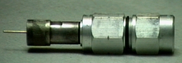
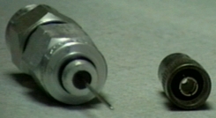
Note: many N connctors have a larger thread size for the compression collar. You need the ones with the smaller
threads for this. John notes that UG-21D/U, UG-21E/U, and UG-1185/U had larger threads and would not work...You
can also adapt a PL-259. Just cut off the back of the PL-259 up to the threads. Then use just the threaded portion
of the knurled cover to make a rigid connection. Then solder the center pin as usual. You might even silver solder
the threads for a perfect ground.
![]()